5-57
STANDARD AND PTS INTERRUPTS
11. Enable the PTS and conventional interrupts.
— Use the EI instruction to enable all standard interrupts and the EPTS instruction to
enable the PTS.
12. Toggle the RXD input to start the reception. The EPA will generate a conventional
interrupt. This interrupt service routine should be the same as the end-of-PTS rountine.
The service routine can determine if this is a start reception interrupt or a end-of-PTS
interrupt by reading the EPA0_CON register. If the register is set to capture mode, then
this is the start reception interrupt.
The interrupt service routine contains the following steps.
1. Reconfigure the EPA channel to compare mode.
— Set EPA0_CON.6 (selects compare mode).
2. Initialize the first PTS cycle time by writing the time of the first interrupt to EPA0_TIME.
To set-up the correct value, multiply the baud_value (1A0H) by 1.5, add the product to the
current TIMER1 value, and store the result in EPA0_TIME. The baud_value determines
the time to the first PTS interrupt. When the interrupt occurs, the PTS transmits the first
data bit. The baud_value of 1A0H selects a baud rate of 9600. In this example, the value
added to the current TIMER1 value is 270H.
3. Select PTS service for EPA0.
— Set PTSSEL.2.
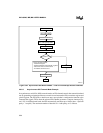
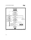
4. The PTS routine begins sampling the data every 1.5 bit times. When PTSCOUNT
decrements to zero, the PTS calls the end-of-PTS interrupt (Figure 5-28). The interrupt
service routine should check to see if a framing or parity error occurred (Figure 5-19 on
page 5-38), clear the DATA registers to prepare for the next reception, reload the
PTSCOUNT and PTSCON1 registers, and reconfigure the EPA channel to select capture
on falling edge mode. Note that PTS service is not enabled for the EPA channel at this time
because the next interrupt must be a conventional interrupt.
5. To determine when all bytes have been transmitted, create a loop routine to check the
status of the RXDDONE flag.


