11-7
EVENT PROCESSOR ARRAY (EPA)
where:
prescaler_divisor is the clock prescaler divisor from the T
x
CONTROL registers (see
“Timer 1 Control (T1CONTROL) Register” on page 11-16 and
“Timer 2 Control (T2CONTROL) Register” on page 11-17).
F
XTAL1
is the input frequency on XTAL1.
11.3.1 Cascade Mode (Timer 2 Only)
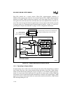
Timer 2 can be used in cascade mode. In this mode, the timer 1 overflow output is used as the
timer 2 clock input. Either the direction control bit of the timer 2 control register or the direction
control assigned to timer 1 controls the count direction. This method, called cascading, can pro-
vide a slow clock for idle mode timeout control or for slow pulse-width modulation (PWM) ap-
plications (see “Generating a Low-speed PWM Output” on page 11-13).
11.3.2 Quadrature Clocking Modes
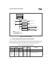
Timer 1 can be used in two quadrature clocking modes. Both modes use the T1CLK and T1DIR
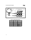
pins as quadrature inputs, as shown in Figure 11-3. External quadrature-encoded signals (two sig-
nals at the same frequency that differ in phase by 90°) are input, and the timer increments or dec-
rements by one count on each rising edge and each falling edge. Because the T1CLK and T1DIR
inputs are sampled by the internal phase clocks, transitions must be separated by at least two state
times for proper operation. The count is clocked by PH2, which is PH1 delayed by one-half pe-
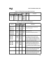
riod. The sequence of the signal edges and levels controls the count direction. Refer to Figure
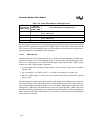
11-4 and Table 11-4 for sequencing information.
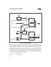
A typical source of quadrature-encoded signals is a shaft-angle decoder, shown in Figure 11-3.
Its output signals X and Y are input to T1CLK and T1DIR, which in turn output signals
X_internal and Y_internal. These signals are used in Figure 11-4 and Table 11-4 to describe the
direction of the shaft.
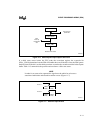
In the default quadrature clocking mode, software must reload the TIMER1 register when timer
1 overflows or underflows. In mode 2 (T1CONTROL.2:0 = 1), timer 1 automatically loads the
value from the T1RELOAD register into the TIMER1 register when an overflow or underflow
occurs. Mode 2 is useful for interfacing to an incremental shaft encoder that turns in only one di-
rection. For this application, initialize T1RELOAD with a value that is one less than the encoder’s
resolution. This method allows timer 1 to track the absolute position of the shaft encoder with no
software overhead.


