


8XC196MC, MD, MH USER’S MANUAL
16-14
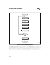
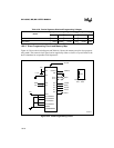
16.7.2 Power-up and Power-down Sequences
When you are ready to begin programming, follow these power-up and power-down procedures.
WARNING
Failure to observe these warnings will cause permanent device damage.
• Voltage must not be applied to V
PP
while V
CC
is low.
• The V
PP
voltage must be within 1 volt of V
CC
while V
CC
is less than 4.5 volts. V
PP
must not
go above 4.5 volts until V
CC
is at least 4.5 volts.
• The V
PP
maximum voltage must not be exceeded.
• EA# must reach programming voltage before V
PP
does so.
• The PMODE pins (P0.7:4) must be in their desired states before RESET# rises.
• All voltages must be within the ranges specified in the datasheet and the oscillator must be
stable before RESET# rises.
• The power supplies to the V
CC
, V
PP
, EA# and RESET# pins must be well regulated and free
of glitches and spikes.
• All V
SS
pins must be well grounded.
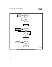
16.7.2.1 Power-up Sequence
1. Hold RESET# low while V
CC
stabilizes. Allow V
PP
and EA# to float during this time.
2. After V
CC
and the oscillator stabilize, continue to hold RESET# low and apply V
PP
voltage
to EA#.
3. After EA# stabilizes, apply V
PP
voltage (+12.5V) to the V
PP
pin.
4. Set the PMODE value to select a programming algorithm.
5. Bring the RESET# pin high.
6. Complete the selected programming algorithm.
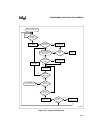
16.7.2.2 Power-down Sequence
1. Assert the RESET# signal and hold it low throughout the powerdown sequence.
2. Remove the V
PP
voltage from the V
PP
pin and allow the pin to float.
3. Remove the V
PP
voltage from the EA# pin and allow the pin to float.
4. Turn off the V
CC
supply and allow time for it to reach 0 volts.