15-23
INTERFACING WITH EXTERNAL MEMORY
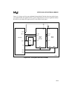
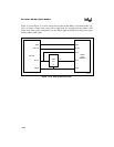
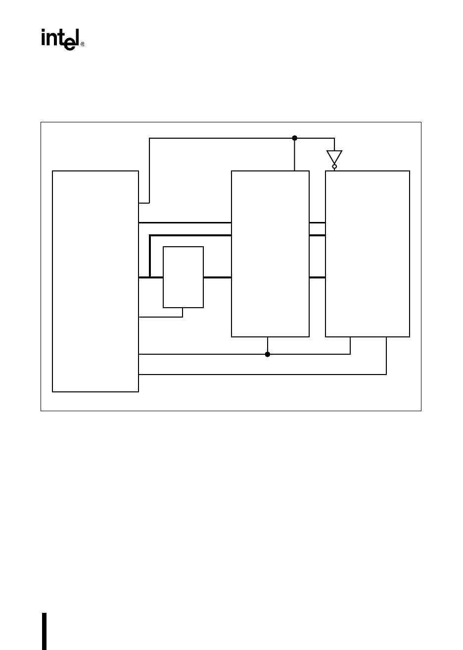
Figure 15-12 shows an 8-bit system with both flash and RAM. The flash is the lower half of mem-
ory, and the RAM is the upper half. This system configuration uses the most-significant address
bit (AD15) as the chip-select signal and ALE as the address-latch signal.
Figure 15-12. 8-bit System with Flash and RAM
AD14:8
AD7:0
ALE
RD#
WR#
8XC196
74AC
373
32K×8
Flash
(28F256)
8K×8
RAM
A7:0
A14:8
D7:0
OE#
OE# WE#
CS# CS#
A3140-01
A7:0
D7:0
A12:8
AD15
LE
A7:0


