


8XC196MC, MD, MH USER’S MANUAL
5-24
5.6 INITIALIZING THE PTS CONTROL BLOCKS
Each PTS interrupt requires a block of data, in register RAM, called the PTS control block
(PTSCB). The PTSCB identifies which PTS microcode routine will be invoked and sets up the
specific parameters for the routine. You must set up the PTSCB for each interrupt source before
enabling the corresponding PTS interrupts.
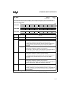
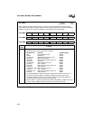
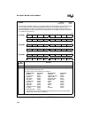
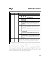
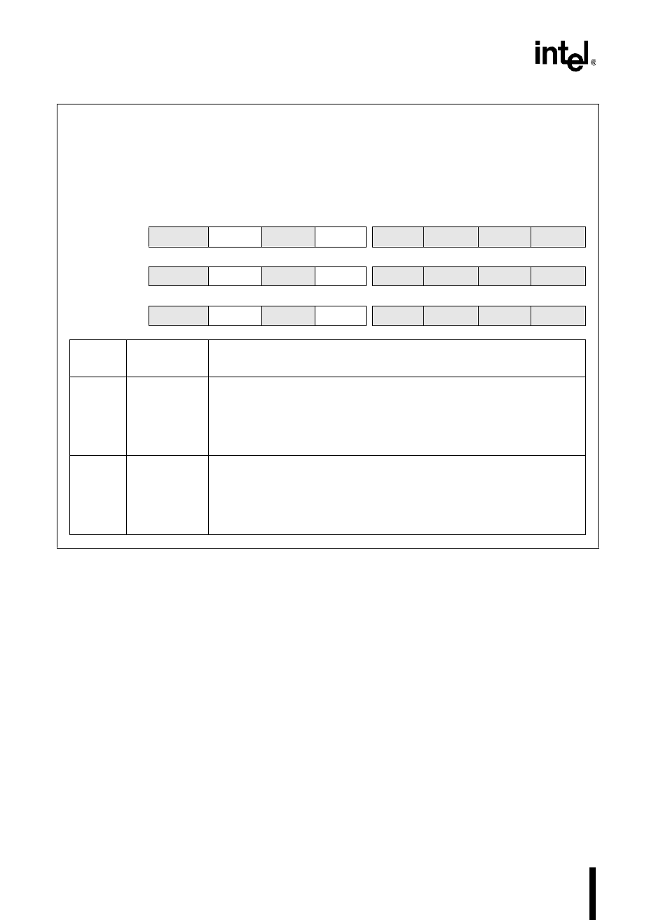
2 OVRTM2 Timer 2 Overflow/Underflow
When set, this bit indicates a pending timer 2 overflow/underflow interrupt.
The timer 2 and timer 1 overflow/underflow interrupts are associated with
the overflow/underflow timer interrupt (OVRTM). Setting INT_MASK.0
enables OVRTM. Setting PI_MASK.2 enables OVRTM2.
0 OVRTM1 Timer 1 Overflow/Underflow
When set, this bit indicates a pending timer 1 overflow/underflow interrupt.
The timer 1 and timer 2 overflow/underflow interrupts are associated with
the overflow/underflow timer interrupt (OVRTM). Setting INT_MASK.0
enables OVRTM. Setting PI_MASK.0 enables OVRTM1.
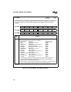
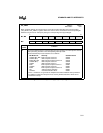
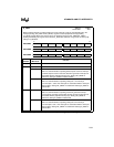
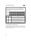
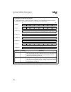
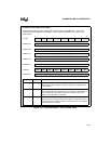
PI_PEND (Continued)
Address:
Reset State:
1FBEH
AAH
When hardware detects a pending peripheral or timer interrupt, it sets the corresponding bit in the
interrupt pending (INT_PEND or INT_PEND1) registers and the peripheral interrupt pending
(PI_PEND) register. When the vector is taken, the hardware clears the INT_PEND/INT_PEND1
pending bit. Reading this register clears all the PI_PEND bits. Software can generate an interrupt by
setting a PI_PEND bit.
7 0
8XC196MC
———WG —OVRTM2 — OVRTM1
7 0
8XC196MD
— COMP5 —WG —OVRTM2 — OVRTM1
7 0
8XC196MH
—SP1—SP0 —OVRTM2 — OVRTM1
Bit
Number
Bit
Mnemonic
Function
Figure 5-12. Peripheral Interrupt Pending (PI_PEND) Register (Continued)