


8XC196MC, MD, MH USER’S MANUAL
2-2
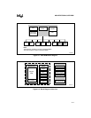
2.3 FUNCTIONAL OVERVIEW
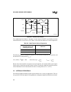
Figure 2-1 shows the major blocks within the microcontroller. The core of the microcontroller
(Figure 2-2) consists of the central processing unit (CPU) and memory controller. The CPU con-
tains the register file and the register arithmetic-logic unit (RALU). A 16-bit internal bus connects
the CPU to both the memory controller and the interrupt controller. An extension of this bus con-
nects the CPU to the internal peripheral modules. In addition, an 8-bit internal bus transfers in-
struction bytes from the memory controller to the instruction register in the RALU.
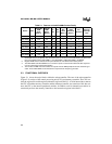
Table 2-1. Features of the 8XC196M
x
Product Family
Device Pins
OTPROM/
ROM
Bytes
(Note 1)
Register
RAM
Bytes
(Note 2)
I/O
Pins
EPA
Pins
SIO
Ports
(Note 3)
PWM
Channels
(Note 4)
A/D
Channels
External
Interrupt
Pins
8XC196MH 84 32 K 744 52 6 2 8 8 1
8XC196MH 80 32 K 744 52 6 2 8 8 1
8XC196MH 64 32 K 744 50 6 2 7 8 1
8XC196MC 84 16 K 488 53 8 0 8 13 1
8XC196MC 80 16 K 488 53 8 0 8 13 1
8XC196MC 64 16 K 488 49 7 0 7 12 1
8XC196MD 84 16 K 488 64 12 0 9 14 1
8XC196MD 80 16 K 488 64 12 0 9 14 1
NOTES:
1. Nonvolatile memory is optional. The second character of the device name indicates the presence and
type of nonvolatile memory. 80C196M
x
= none; 83C196M
x
= ROM; 87C196M
x
= OTPROM.
2. Register RAM amounts include the 24 bytes allocated to core SFRs and the stack pointer.
3. The 8XC196MC and 8XC196MD have no serial I/O ports, but have PTS modes that allow asynchro-
nous or synchronous serial communication.
4. The number of PWM channels includes the outputs from the PWM peripheral and the waveform gen-
erator. For the 8XC196MD, it also includes the output from the frequency generator.