8XC196MC, MD, MH USER’S MANUAL
9-6
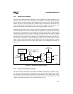
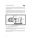
The protection circuitry (Figure 9-3) monitors the EXTINT pin. When it detects a valid event on
the input, it simultaneously disables the outputs and generates an EXTINT interrupt request. Soft-
ware can also disable the outputs by clearing the enable outputs (EO) bit in the protection
(WG_PROTECT) register.
For the 8XC196MC and 8XC196MD, disabled outputs go to their inactive states based on the
programmed polarity. The protection circuitry of the 8XC196MH operates in the same way as
that of the 8XC196MC and 8XC196MD, but it allows you to choose the method used to disable
the outputs. It can either place outputs in their inactive states, as the other devices do, or it can
apply weak pull-ups to them. The protection type (PT) bit in the protection register controls the
method.
Figure 9-3. Protection Circuitry
9.3.4 Register Buffering and Synchronization
The WG_RELOAD, WG_COMPx, and WG_OUTPUT registers are buffered; you read and write
the buffers rather than the registers. The waveform generator updates the registers synchronously
to prevent erroneous or nonsymmetrical duty cycles.
When you write to the WG_COMPx buffers while the counter is stopped (either when the counter
register is zero or when the enable counter bit in the control register is clear), the registers are
updated one-half state time later.
A2661-01
EO Bit
Register
Transition
Detector
Q
Pulse
DP
R
S
00
01
10
11
Falling
Rising
Low
High
OD#
ES, IT
CPU Read EOCPU Write EO
CPU Bus
EXTINT
Interrupt
Request
Level
Sampler
EXTINT
F
XTAL1


