


8XC196MC, MD, MH USER’S MANUAL
10-6
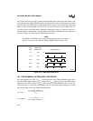
10.5 PROGRAMMING THE DUTY CYCLE
The values written to the PWMx_CONTROL and PWM_PERIOD registers control the width of
the high pulse, effectively controlling the duty cycle. The 8-bit value written to the control regis-
ter is loaded into a buffer, and this value is used during the next period. Use the following duty
cycle formula to calculate a desired duty cycle for given values of PWMx_CONTROL and
PWM_PERIOD, and then write these values to the appropriate registers.
Duty Cycle (in %) =
Pulsewidth (in µs) =
where:
PWM
x
_CONTROL = 8-bit value to load into the PWM
x
_CONTROL register
PWM_PERIOD = 8-bit value to load into the PWM_PERIOD register
Pulsewidth = width of each high pulse
T
PWM
= output period on the PWM pin, in µs
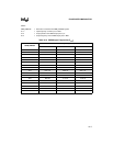
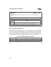
PWM_PERIOD
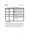
Address:
Reset State:
1FB4H
00H
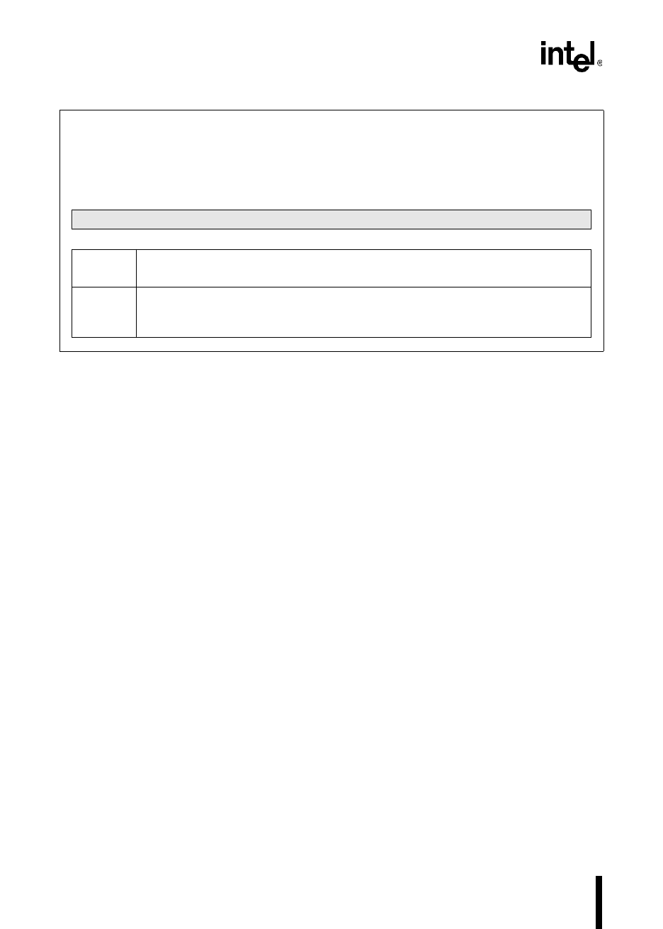
The PWM period (PWM_PERIOD) register controls the period of the PWM outputs. It contains a value
that determines the number of state counts necessary for incrementing the PWM counter. The value
of PWM_PERIOD is loaded into the PWM period count register whenever the count equals zero.
7 0
PWM Period
Bit
Number
Function
7:0 PWM Period
This register controls the period of the PWM outputs. The value of PWM_PERIOD is
loaded into the PWM period count register whenever the count equals zero.
Figure 10-3. PWM Period (PWM_PERIOD) Register
PWM
x
_CONTROL
PWM_PERIOD 1+
-------------------------------------------------------
100×
Duty Cycle T
PWM
×
100
------------------------------------------------