


8XC196MC, MD, MH USER’S MANUAL
5-56
2. Set-up the stack pointer.
3. Reset all interrupt mask registers.
— Clear INT_MASK, INT_MASK1and PI_MASK.
4. Initialize P2.0 to function as the RXD signal.
— Set P2_DIR.0 (selects input).
— Clear P2_MODE.0 (selects LSIO function).
— Set P2_REG.0 (initializes RXD input to “1”).
5. Initialize and enable the timer; select up counting, internal clock, and prescaler disabled.
— Set T1CONTROL bits 6 and 7 (Figure 11-8 on page 11-16).
6. Initialize the PTSCB as shown in Table 5-16.
7. Enable EPA0 interrupt.
— Set INT_MASK.2.
8. Load the number of bytes to transmit into the user_defined transmit count register
(R_COUNT) and clear the user-defined reception-done flag (RXDDONE).
— LD R_COUNT, #16
— CLRB RXDDONE
9. Select PTS service for EPA0.
— Set PTSSEL.2.
10. Set-up EPA0 to capture on falling edges.
— Set EPA0_CON.4 (Figure 11-10 on page 11-19).
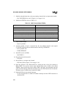
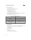
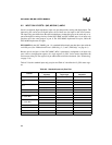
Table 5-16. ASIO Receive Mode PTSCBs
PTSCB1 PTSCB2
PTSVEC (H) = pointer to PTSCB2 Unused
PTSVEC (L) = pointer to PTSCB2 SAMPTIME = 01H
BAUD (H) = 01H DATA (H) = 00H (clear register to receive data)
BAUD (L) = ) A0H DATA (L) = 00H (clear register to receive data)
EPAREG (H) = 1FH (EPA0_TIME) PTSCON1 = 60H (enable odd parity)
EPAREG (L) = 42H (EPA0_TIME) PORTMASK = 01H (P2.0 = RXD)
PTSCON = 21H (SSIO receive mode, majority
sampling)
PORTREG (H) = 1FH (P2_PIN)
PTSCOUNT = 0AH (receive 8 data bits, 1 parity bit) PORTREG (L) = D6H (P2_PIn)