8XC196MC, MD, MH USER’S MANUAL
9-8
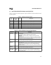
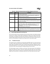
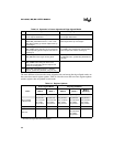
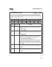
The main differences between the center-aligned modes and among the edge-aligned modes are
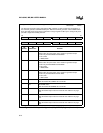
the events that control register updates. Table 9-4 lists the events that can cause register updates
and the registers that are updated in each mode.
Table 9-3. Operation in Center-aligned and Edge-aligned Modes
Step Center-aligned Modes Edge-aligned Modes
1 Load WG_COUNTER with WG_RELOAD.
Leave outputs deasserted.
Load WG_COUNTER with 0001H.
Leave outputs deasserted.
2 When counter is enabled, begin counting down.
When WG_COUNTER reaches 1, wait 1 state,
then begin counting up. Assert outputs when up
count begins.
When counter is enabled, begin counting up.
Assert outputs when up count begins.
3 When WG_COUNTER reaches the
WG_COMP
x
value during the up count, deassert
the corresponding phase’s outputs and continue
counting up.
When WG_COUNTER reaches the
WG_COMP
x
value, deassert the corresponding
phase’s outputs and continue counting up.
4 When WG_COUNTER reaches the
WG_RELOAD value, begin counting down.
When WG_COUNTER reaches the
WG_RELOAD value, update WG_RELOAD and
go to step 1.
5 When WG_COUNTER reaches the
WG_COMP
x
value during the down count,
assert the corresponding phase’s outputs and
continue counting down.
6 When WG_COUNTER reaches 1, deassert
outputs, update WG_RELOAD, and go to step 1.
Table 9-4. Register Updates
Event
Center-aligned Modes Edge-aligned Modes
Mode 0 Mode 1 Mode 2 Mode 3
Mode 4
(MH Only)
Registers Updated Registers Updated
WG_COUNTER
= WG_RELOAD
WG_RELOAD
WG_COUNTER
WG_COMP
x
WG_OUTPUT
†
WG_RELOAD
WG_COUNTER
WG_COMP
x
WG_OUTPUT
†
WG_RELOAD
WG_COUNTER
WG_COMP
x
WG_OUTPUT
†
WG_RELOAD
WG_COUNTER
WG_COMP
x
WG_OUTPUT
†
WG_RELOAD
WG_COUNTER
WG_COMP
x
WG_OUTPUT
†
WG_COUNTER = 1 — WG_COMP
x
———
EPA event
WG_OUTPUT
†
WG_OUTPUT
†
WG_OUTPUT
†
WG_RELOAD
WG_COUNTER
WG_COMP
x
WG_OUTPUT
†
WG_OUTPUT
†
†
The WG_OUTPUT register is updated under these conditions if its synchronization bit is set;
otherwise, changes take effect immediately.


