


8XC196MC, MD, MH USER’S MANUAL
5-16
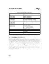
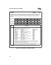
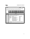
INT_MASK1
Address:
Reset State:
0013H
00H
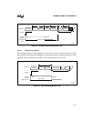
The interrupt mask 1 (INT_MASK1) register enables or disables (masks) individual interrupt requests.
(The EI and DI instructions enable and disable servicing of all maskable interrupts.) INT_MASK1 can
be read from or written to as a byte register. PUSHA saves this register on the stack and POPA
restores it.
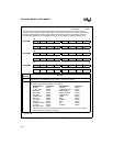
7 0
8XC196MC
NMI EXTINT PI — — — COMP3 EPA3
7 0
8XC196MD
NMI EXTINT PI EPA5 COMP4 EPA4 COMP3 EPA3
7 0
8XC196MH
NMI EXTINT WG SPI RI1 RI0 TI1 TI0
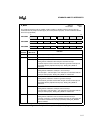
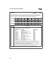
Bit
Number
Function
7:0
†
Setting a bit enables the corresponding interrupt.
The standard interrupt vector locations are as follows:
Bit Mnemonic Interrupt Standard Vector
NMI Nonmaskable Interrupt 203EH
EXTINT EXTINT pin 203CH
PI (MC, MD)
††
Multiplexed Peripheral Interrupt 203AH
WG (MH) Waveform Generator 203AH
EPA5 (MD) EPA Capture/Compare Channel 5 2038H
SPI (MH)
†††
Serial Port 2038H
COMP4 (MD) EPA Compare Channel 4 2036H
RI1 (MH) SIO 1 Receive 2036H
EPA4 (MD) EPA Capture/Compare Channel 4 2034H
RI0 (MH) SIO 0 Receive 2034H
COMP3 (MC, MD) EPA Compare Channel 3 2032H
TI1 (MH) SIO 1 Transmit 2032H
EPA3 (MC, MD) EPA Capture/Compare Channel 3 2030H
TI0 (MH) SIO 0 Transmit 2030H
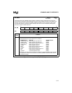
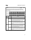
††
The waveform generator and the EPA compare-only channel 5 can generate this
interrupt. Write to PI_MASK to enable the interrupt sources; read PI_PEND to
determine which source caused the interrupt.
†††
SIO 0 and SIO 1 can generate this interrupt. Write to PI_MASK to enable the interrupt
sources; read PI_PEND to determine which source caused the interrupt.
†
On the 8XC196MC device bits 4–3 are reserved. For compatibility with future devices, write zeros to
these bits.
Figure 5-8. Interrupt Mask 1 (INT_MASK1) Register