


12-7
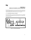
ANALOG-TO-DIGITAL (A/D) CONVERTER
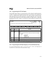
12.4.4 Programming the A/D Command Register
The A/D command register controls the operating mode, the analog input channel, and the con-
version trigger.
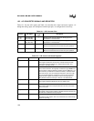
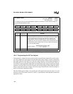
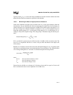
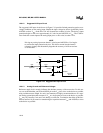
AD_TIME
Address:
Reset State:
1FAFH
FFH
The A/D time (AD_TIME) register programs the sample window time and the conversion time for each
bit. This register programs the speed at which the A/D can run — not the speed at which it can convert
correctly. Consult the data sheet for recommended values. Initialize the AD_TIME register before
initializing the AD_COMMAND register. Do not write to this register while a conversion is in progress;
the results are unpredictable.
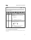
7 0
SAM2 SAM1 SAM0 CONV4 CONV3 CONV2 CONV1 CONV0
Bit
Number
Bit
Mnemonic
Function
7:5 SAM2:0 A/D Sample Time
These bits specify the sample time. Use the following formula to
compute the sample time.
where:
SAM = 1 to 7
T
SAM
= the sample time, in µsec, from the data sheet
F
XTAL1
= the input frequency on XTAL1, in MHz
4:0 CONV4:0 A/D Convert Time
These bits specify the conversion time for each bit. Use the following
formula to compute the conversion time.
where:
CONV= 2 to 31
T
CONV
= the conversion time, in µsec, from the data sheet
F
XTAL1
= the input frequency on XTAL1, in MHz
B = the number of bits to be converted (8 or 10)
Figure 12-4. A/D Time (AD_TIME) Register
SAM
T
SAM
F
XTAL1
× 2–
8
-------------------------------------------------
=
CONV
T
CONV
F
XTAL1
× 3–
2B×
----------------------------------------------------
1–=