


8XC196MC, MD, MH USER’S MANUAL
9-18
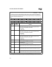
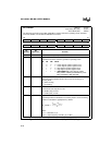
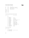
WG_CONTROL
Address:
Reset State (MC, MD):
Reset State (MH):
1FCCH
00C0H
8000H
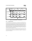
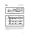
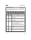
The waveform generator control (WG_CONTROL) register controls the operating mode, dead time,
and count direction, and enables and disables the counter.
15 8
— M2 M1 M0 CS EC DT9 DT8
7 0
DT7 DT6 DT5 DT4 DT3 DT2 DT1 DT0
Bit
Number
Bit
Mnemonic
Function
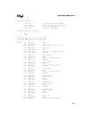
15 — Reserved; for compatibility with future devices, write zero to this bit.
14:12 M2:0 Operating Mode
This field controls the waveform generator’s operating mode.
M2 M1 M0 Mode
0000center-aligned; update registers once
0011center-aligned; update registers twice
0102edge-aligned; update registers once
0113edge-aligned; update registers twice
1114(8XC196MH only) edge-aligned; update
WG_COMP
x
and WG_COUNTER only when
WG_COUNTER = WG_RELOAD
11 CS Counter Status
This read-only bit indicates whether the counter is counting up or
counting down.
0 = down counting
1 = up counting
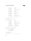
10 EC Enable Counter
This bit starts and stops the counter.
0 = disable (stop) counter
1 = enable (start) counter
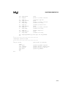
9:0 DT9:0 Dead-time
This field specifies the dead-time for all three phases. Use the following
formula to calculate the appropriate DT_VALUE.
where:
T
DEAD
= dead-time, in µs
F
XTAL1
= input frequency on XTAL1 pin, in MHz
Figure 9-12. Waveform Generator Control (WG_CONTROL) Register
DT_VALUE
T
DEAD
F
XTAL1
×
2
------------------------------------------
=