


8XC196MC, MD, MH USER’S MANUAL
7-10
7.4 PROGRAMMING THE SERIAL PORT
To use the SIO port, you must configure the port pins to serve as special-function signals and set
up the SIO channels.
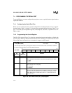
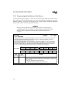
7.4.1 Configuring the Serial Port Pins
Before you can use the serial port, you must configure the associated port pins to serve as special-
function signals. Table 7-1 on page 7-2 lists the pins associated with the serial port. Table 7-2 on
page 7-2 lists the port configuration registers, and Chapter 6, “I/O Ports,” explains how to con-
figure the pins.
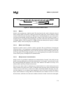
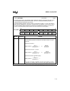
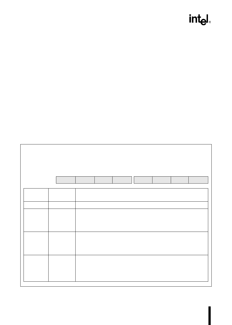
7.4.2 Programming the Control Register
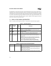
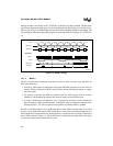
The SPx_CON register (Figure 7-6) selects the communication mode and enables or disables the
receiver, parity checking, and nine-bit data transmissions. Selecting a new mode resets the serial
I/O port and aborts any transmission or reception in progress on the channel.
SP
x
_CON
x
= 0–1 (8XC196MH)
Address:
Reset State:
1F83H, 1F8BH
00H
The serial port control (SP
x
_CON) register selects the communications mode and enables or disables
the receiver, parity checking, and nine-bit data transmission.
7 0
8XC196MH
M2 DIR PAR TB8 REN PEN M1 M0
Bit
Number
Bit
Mnemonic
Function
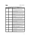
7 M2 See description for bits 0 and 1.
6 DIR Synchronous Clock Direction
This bit determines the direction of the clock during synchronous mode.
0 = output
1 = input
5 PAR Parity Selection Bit
This bit selects even or odd parity.
0 = even parity
1 = odd parity
4 TB8 Transmit Ninth Data Bit
This is the ninth data bit that will be transmitted in mode 2 or 3. This bit is
cleared after each transmission, so it must be set before SBUF
x
_TX is
written. When parity is enabled (SP
x
_CON.2 = 1), this bit takes on the
even parity value.
Figure 7-6. Serial Port Control (SP
x
_CON) Register