


8XC196MC, MD, MH USER’S MANUAL
B-26
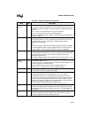
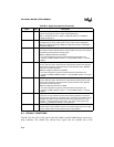
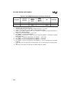
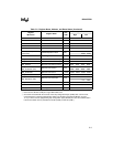
— XTAL1 Osc input, HiZ — Osc input, HiZ Osc input, HiZ
— XTAL2 Osc output,
LoZ0/1
— Osc output,
LoZ0/1
(Note 5)
NOTES:
1. These pins also control test mode entry.
2. If Disable Reset Out = 0, pin is LoZ0. Else if Disable Reset Out =1, pin is HiZ.
3. If EA# = 0, Port 3 and Port 4 = HiZ. If EA# = 1, Port 3 and Port 4 = ODIO.
4. If EA# = 1, pin is WK1. If EA# = 0, P5.0, P5.3, and P5.5 are configured as outputs and function as
ADV#, RD#, or BHE# respectively.
5. If XTAL1 = 1, pin is LoZ0. If XTAL1 = 0, pin is LoZ1.
6. If P5_MODE.0 = 0, port is as programmed.
If P5_MODE.0 = 1 and CCR.3 = 1 (ALE mode), pin is LoZ0. If P5_MODE.0 = 1 and CCR.3 = 0 (ADV#
mode), pin is LoZ1.
7. If P5_MODE.1 = 0, port is as programmed. If P5_MODE.1 = 1, pin is LoZ0.
8. If P5_MODE.
y
= 0, port is as programmed. If P5_MODE.
y
= 1, pin is LoZ1.
9. If P5_MODE.
y
= 0, port is as programmed. If P5_MODE.
y
= 1, pin is HiZ.
10. If P
x
_MODE.
y
= 0, port is as programmed. If P
x
_MODE.
y
= 1, pin is as specified by the associated
peripheral.
11. If output port, pin is as programmed. If special function, pin is as specified by the associated periph-
eral.
12. The values in this column are valid until your software writes to P
x
_MODE.
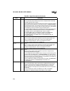
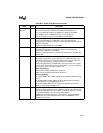
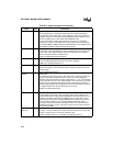
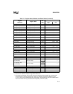
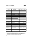
Table B-9. 8XC196MH Default Signal Conditions (Continued)
Port Signals
Alternate
Functions
During
RESET#
Active
Upon
RESET#
Inactive
(Note 12)
Idle Powerdown