A-33
INSTRUCTION SET REFERENCE
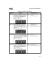
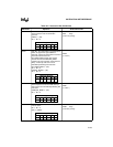
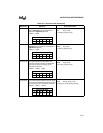
SHLL SHIFT DOUBLE-WORD LEFT. Shifts the
destination double-word operand to the left
as many times as specified by the count
operand. The count may be specified either
as an immediate value in the range of 0 to 15
(0FH), inclusive, or as the content of any
register (10H – 0FFH) with a value in the
range of 0 to 31 (1FH), inclusive. The right
bits of the result are filled with zeros. The last
bit shifted out is saved in the carry flag.
Te mp
← (COUNT)
do while Temp
≠ 0
C
← High order bit of (DEST)
(DEST)
← (DEST) × 2
Temp
← Temp – 1
end_while
SHLL lreg, #count
(00001101) (count) (lreg)
or
SHLL lreg, breg
(00001101) (breg) (lreg)
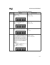
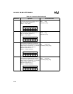
PSW Flag Settings
ZNCVVTST
✓✓✓✓↑—
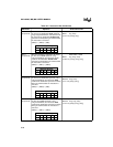
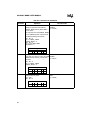
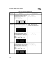
SHR LOGICAL RIGHT SHIFT WORD. Shifts the
destination word operand to the right as
many times as specified by the count
operand. The count may be specified either
as an immediate value in the range of 0 to 15
(0FH), inclusive, or as the content of any
register (10H – 0FFH) with a value in the
range of 0 to 31 (1FH), inclusive. The left bits
of the result are filled with zeros. The last bit
shifted out is saved in the carry flag.
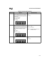
Te mp
← (COUNT)
do while Temp
≠ 0
C
← Low order bit of (DEST)
(DEST)
← (DEST)/2
Te mp
← Temp – 1
end_while
SHR wreg, #count
(00001000) (count) (wreg)
or
SHR wreg, breg
(00001000) (breg) (wreg)
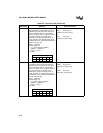
NOTES: This instruction clears the
sticky bit flag at the beginning
of the instruction. If at any time
during the shift a “1” is shifted
into the carry flag and another
shift cycle occurs, the instruc-
tion sets the sticky bit flag.
In this operation, (DEST)/2 rep-
resents unsigned division.
PSW Flag Settings
ZNCVVTST
✓0✓0—✓
Table A-6. Instruction Set (Continued)
Mnemonic Operation Instruction Format


