13-3
MINIMUM HARDWARE CONSIDERATIONS
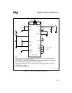
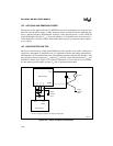
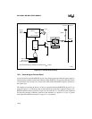
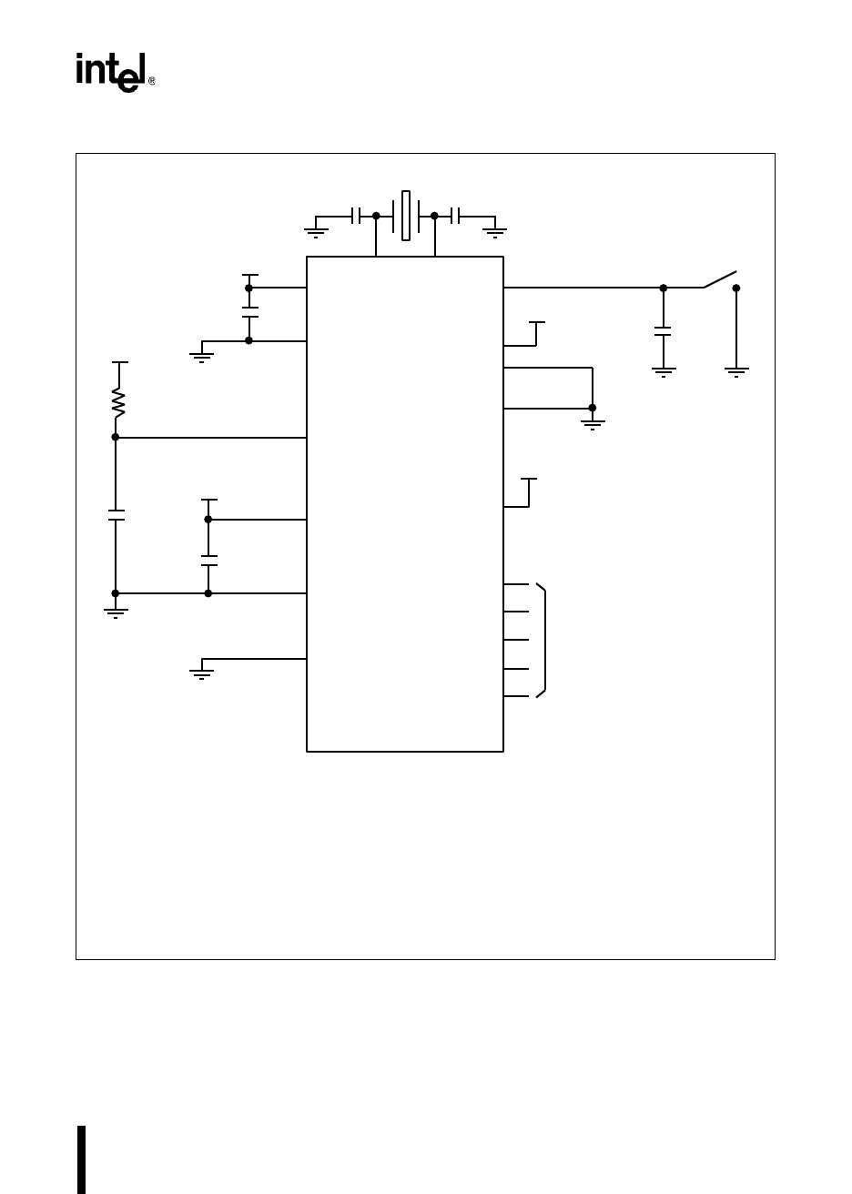
Figure 13-1. Minimum Hardware Connections
ALE
ANGND
INST
XTAL1XTAL2
V
CC
(Note 2)
0.01 µF
BUSWIDTH
NMI
READY
V
CC
Port 5 / Bus Control
(Note 4)
20 pF 20 pF
(Note 1)
4.7 µF
+
V
CC
+
1 µF
1 M
RESET#
BHE#
WR#
RD#
EA#
+
1 µF
V
CC
V
CC
A2643-03
V
SS
V
PP
V
REF
8XC196 Device
V
CC
Notes:
1. See the datasheet for the oscillator frequency range (F
XTAL1
) and the crystal manufacturer's
datasheet for recommended load capacitors.
2. The number of V
CC
and V
SS
pins varies with package type (see datasheet). Be sure to connect
each V
CC
pin to the supply voltage and each V
SS
pin to ground.
3. Connect the RC network to V
PP
only if powerdown mode will be used. Otherwise, connect V
PP
to V
CC.
4. No connection is required.
5. Tie all input-only port pins to V
SS.
(Note 3)
Input-only
Port Pins
(Note 5)


