


6-1
CHAPTER 6
I/O PORTS
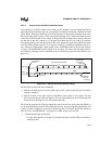
I/O ports provide a mechanism to transfer information between the device and the surrounding
system circuitry. They can read system status, monitor system operation, output device status,
configure system options, generate control signals, provide serial communication, and so on.
Their usefulness in an application is limited only by the number of I/O pins available and the
imagination of the engineer.
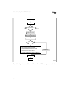
6.1 I/O PORTS OVERVIEW
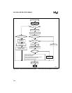
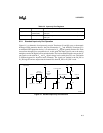
Standard I/O port registers are located in the SFR address space and they can be windowed. Mem-
ory-mapped I/O port registers are located in memory-mapped address space. Memory-mapped
registers must be accessed with indirect or indexed addressing; they cannot be windowed. All
ports can provide low-speed input/output pins or serve alternate functions. Table 6-1 provides an
overview of the device I/O ports. The remainder of this chapter describes the ports in more detail
and explains how to configure the pins. The chapters that cover the associated peripherals discuss
using the pins for their special functions.
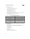
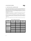
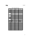
Table 6-1. Device I/O Ports
Port Bits Type Direction Associated Peripheral(s)
Port 0 8 Standard Input-only
A/D converter (MC, MD)
A/D converter, EPA (MH)
Port 1
5 (MC)
8 (MD)
Standard Input-only
A/D converter, EPA (MC, MD)
P1.7:6 are digital input-only
channels for the 8XC196MD.
4 (MH) Standard Bidirectional SIO
Port 2 8 Standard Bidirectional
EPA and timers (MC, MD)
EPA and timers, SIO (MH)
Port 3 8 Memory-mapped Bidirectional Address/data bus
Port 4 8 Memory-mapped Bidirectional Address/data bus
Port 5 8 Memory-mapped Bidirectional Bus control
Port 6 8 Standard Output-only PWM, waveform generator
Port 7 (MD) 8 Standard Bidirectional
EPA, frequency generator
P7.6:4 are low-speed input/output pins
only; they have no peripheral functions.