


8XC196MC, MD, MH USER’S MANUAL
5-38
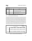
transmitted or received including the parity and stop bits in the asynchronous modes. The serial
I/O modes require two PTS control blocks to configure all options (see Figures 5-19 and 5-20).
These blocks need not be contiguous, but they must each be located in register RAM on a quad-
word boundary. See AP-483, Application Examples Using the 8XC196MC/MD Microcontroller,
for application examples with code.
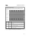
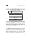
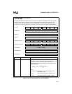
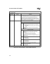
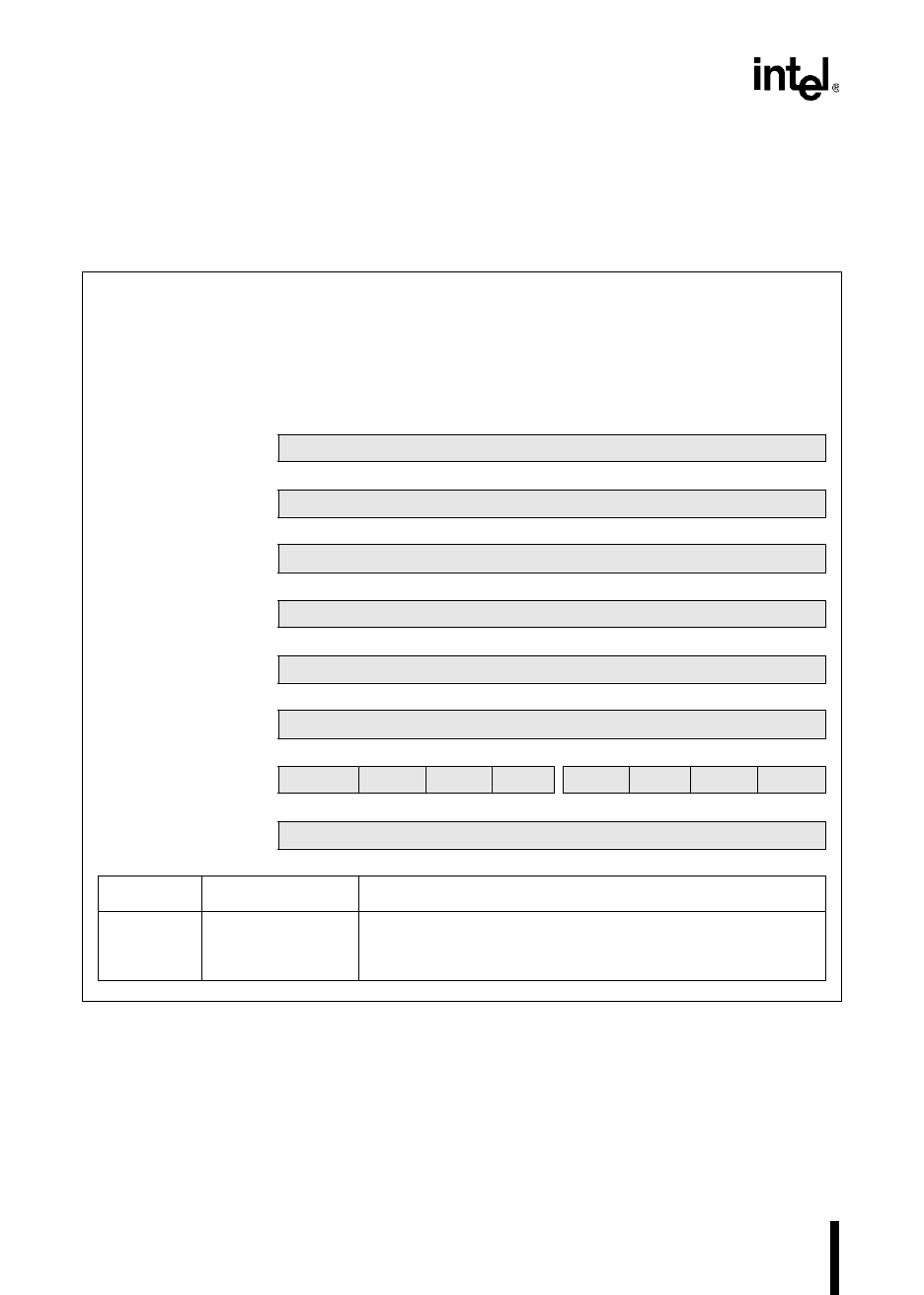
PTS Serial I/O Mode Control Block 1
(8XC196MC, MD)
The PTS control block 1 contains pointers to both the second PTS control block (PTSVEC) and the
EPA time register that sets the baud rate (EPAREG). It also contains a 16-bit value that is used to
calculate the baud rate, a control register (PTSCON), and a consecutive PTS cycle count
(PTSCOUNT).
15 8
PTSVEC (H)
SIO PTSCB2 Base Address Pointer (high byte)
7 0
PTSVEC (L)
SIO PTSCB2 Base Address Pointer (low byte)
15 8
BAUD (H)
Baud Value (high byte)
7 0
BAUD (L)
Baud Value (low byte)
15 8
EPAREG (H)
EPA Time Register Address (high byte)
7 0
EPAREG (L)
EPA Time Register Address (low byte)
7 0
PTSCON
M2 M1 M0 SA1 0 0 SA0 MAJ
7 0
PTSCOUNT
Consecutive PTS Cycles
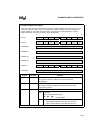
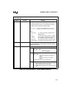
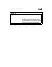
Register Location Function
PTSVEC PTSCB1 + 6 SIO PTSCB2 Base Address Pointer
This register contains the base address of the second PTS
control block for serial I/O mode.
Figure 5-19. PTS Control Block 1 – Serial I/O Mode