5-19
STANDARD AND PTS INTERRUPTS
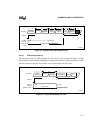
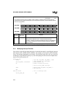
Note that location 2002H in the interrupt vector table must be loaded with the value of the label
AD_DONE_ISR before the interrupt request occurs and that the A/D conversion complete inter-
rupt must be enabled for this routine to execute.
This routine, like all interrupt service routines, is handled in the following manner:
1. After the hardware detects and prioritizes an interrupt request, it generates and executes an
interrupt call. This pushes the program counter onto the stack and then loads it with the
contents of the vector corresponding to the highest priority, pending, unmasked interrupt.
The hardware will not allow another interrupt call until after the first instruction of the
interrupt service routine is executed.
2. The PUSHA instruction saves the contents of the PSW, INT_MASK, INT_MASK1, and
window selection register (WSR) onto the stack and then clears the PSW, INT_MASK,
and INT_MASK1 registers. In addition to the arithmetic flags, the PSW contains the
global interrupt enable bit (I) and the PTS enable bit (PSE). By clearing the PSW and the
interrupt mask registers, PUSHA effectively masks all maskable interrupts, disables
standard interrupt servicing, and disables the PTS. Because PUSHA is a protected
instruction, it also inhibits interrupt calls until after the next instruction executes.
3. The LDB INT_MASK1 instruction enables those interrupts that you choose to allow to
interrupt the service routine. In this example, only EXTINT can interrupt the receive
interrupt service routine. By enabling or disabling interrupts, the software establishes its
own interrupt servicing priorities.
4. The EI instruction re-enables interrupt processing and inhibits interrupt calls until after the
next instruction executes.
5. The actual interrupt service routine executes within the priority structure established by
the software.
6. At the end of the service routine, the POPA instruction restores the original contents of the
PSW, INT_MASK, INT_MASK1, and WSR registers; any changes made to these
registers during the interrupt service routine are overwritten. Because interrupt calls
cannot occur immediately following a POPA instruction, the last instruction (RET) will
execute before another interrupt call can occur.
Notice that the “preamble” and exit code for this routine do not save or restore register RAM. The
interrupt service routine is assumed to allocate its own private set of registers from the lower reg-
ister file. The general-purpose register RAM in the lower register file makes this quite practical.
In addition, the RAM in the upper register file is available via windowing (see “Windowing” on
page 4-12).


