


© Koninklijke Philips Electronics N.V. 2005. All rights reserved.
User manual Rev. 02 — 23 May 2005 93 of 133
Philips Semiconductors
UM10109
P89LPC932A1 User manual
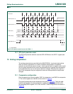
12.7 SPI clock prescaler select
The SPI clock prescalar selection uses the SPR1-SPR0 bits in the SPCTL register (see
Table 7 3
).
13. Analog comparators
Two analog comparators are provided on the P89LPC932A1. Input and output options
allow use of the comparators in a number of different configurations. Comparator
operation is such that the output is a logic 1 (which may be read in a register and/or routed
to a pin) when the positive input (one of two selectable pins) is greater than the negative
input (selectable from a pin or an internal reference voltage). Otherwise the output is a
zero. Each comparator may be configured to cause an interrupt when the output value
changes.
13.1 Comparator configuration
Each comparator has a control register, CMP1 for comparator 1 and CMP2 for comparator
2. The control registers are identical and are shown in Ta bl e 79
.
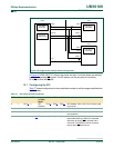
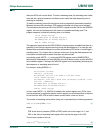
The overall connections to both comparators are shown in Figure 45
. There are eight
possible configurations for each comparator, as determined by the control bits in the
corresponding CMPn register: CPn, CNn, and OEn. These configurations are shown in
Figure 46
.
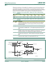
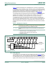
(1) Not defined
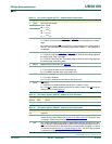
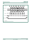
Fig 44. SPI master transfer format with CPHA = 1.
1 2 3 4 5 6 7 8
MSB
LSB
6
1
5
2
4
3
3
4
2
5
1
6
LSB
MSB
MSB
LSB
DORD = 0
DORD = 1
6
1
5
2
4
3
3
4
2
5
1
6
LSB
MSB
002aaa93
7
Clock cycle
SPICLK (CPOL = 0)
SPICLK (CPOL = 1)
MOSI (input)
MISO (output)
SS (if SSIG bit = 0)
DORD = 0
DORD = 1