


© Koninklijke Philips Electronics N.V. 2005. All rights reserved.
User manual Rev. 02 — 23 May 2005 73 of 133
Philips Semiconductors
UM10109
P89LPC932A1 User manual
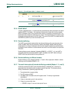
The values for I2SCLL and I2SCLH do not have to be the same; the user can give different
duty cycles for SCL by setting these two registers. However, the value of the register must
ensure that the data rate is in the I
2
C data rate range of 0 to 400 kHz. Thus the values of
I2SCLL and I2SCLH have some restrictions and values for both registers greater than
three PCLKs are recommended.
11.6 I
2
C operation modes
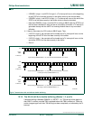
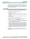
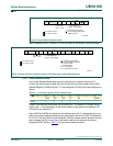
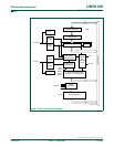
11.6.1 Master Transmitter mode
In this mode data is transmitted from master to slave. Before the Master Transmitter mode
can be entered, I2CON must be initialized as follows:
CRSEL defines the bit rate. I2EN must be set to 1 to enable the I
2
C function. If the AA bit
is 0, it will not acknowledge its own slave address or the general call address in the event
of another device becoming master of the bus and it can not enter slave mode. STA, STO,
and SI bits must be cleared to 0.
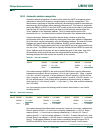
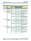
Table 65: I
2
C clock rates selection
Bit data rate (Kbit/sec) at f
osc
I2SCLL+
I2SCLH
CRSEL 7.373 MHz 3.6865 MHz 1.8433 MHz 12 MHz 6 MHz
6 0 - 307 154 - -
7 0 - 263 132 - -
8 0 - 230 115 - 375
9 0 - 205 102 - 333
10 0 369 184 92 - 300
15 0 246 123 61 400 200
25 0 147 74 37 240 120
30 0 123 61 31 200 100
50 0 74 37 18 120 60
60 0 61 31 15 100 50
100 0 37 18 9 60 30
150 0 25 12 6 40 20
200 0 18 9 5 30 15
- 1 3.6 Kbps to
922 Kbps
Timer 1 in
mode 2
1.8 Kbps to
461 Kbps
Timer 1 in
mode 2
0.9 Kbps to
230 Kbps
Timer 1 in
mode 2
5.86 Kbps to
1500 Kbps
Timer 1 in
mode 2
2.93 Kbps to
750 Kbps
Timer 1 in
mode 2
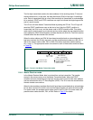
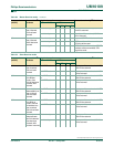
Table 66: I
2
C Control register (I2CON - address D8h)
Bit 7 6 5 4 3 2 1 0
- I2EN STA STO SI AA - CRSEL
value- 1000x- bit rate