


© Koninklijke Philips Electronics N.V. 2005. All rights reserved.
User manual Rev. 02 — 23 May 2005 53 of 133
Philips Semiconductors
UM10109
P89LPC932A1 User manual
When the timer changes direction at the bottom, in this example, it counts …,0001H,
0000H, 0001H,… The CCU Timer overflow interrupt flag is set in the counter CCUCLK
cycle after the transition from 0001H to 0000H.
The status of the TDIR2 bit in TCR20 reflects the current counting direction. Writing to this
bit while operating in symmetrical mode has no effect.
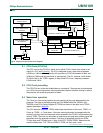
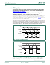
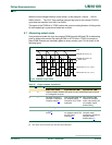
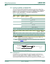
9.7 Alternating output mode
In asymmetrical mode, the user can program PWM channels A/B and C/D as alternating
pairs for bridge drive control. By setting ALTAB or ALTCD bits in TCR20, the output of
these PWM channels are alternately gated on every counter cycle. This is shown in the
following figure:
[1] x = A, B, C, D
[2] ‘ON’ means in the CCUCLK cycle after the event takes place.
Fig 23. Alternate output mode.
Table 37: Output compare pin behavior
OCMx1
[1]
OCMx0
[1]
Output Compare pin behavior
Basic timer mode Asymmetrical PWM Symmetrical PWM
0 0 Output compare disabled. On power-on, this is the default state, and pins
are configured as inputs.
0 1 Set when compare in
operation. Cleared on
compare match.
[2]
Non-Inverted PWM. Set
on compare match.
Cleared on CCU Timer
underflow.
Non-Inverted PWM.
Cleared on compare
match, upcounting. Set
on compare match,
downcounting.
1 0 invalid configuration
1 1 Toggles on compare
match
[2]
Inverted PWM. Cleared
on compare match. Set
on CCU Timer
underflow.
[2]
Inverted PWM. Set on
compare match,
upcounting. Cleared on
compare match,
downcounting.
[2]
TIMER VALUE
002aaa895
0
TOR2
COMPARE VALUE A (or C)
COMPARE VALUE B (or D)
PWM OUTPUT A (or C) (P2.6)
PWM OUTPUT B (or D) (P1.6)