


© Koninklijke Philips Electronics N.V. 2005. All rights reserved.
User manual Rev. 02 — 23 May 2005 32 of 133
Philips Semiconductors
UM10109
P89LPC932A1 User manual
5. Power monitoring functions
The P89LPC932A1 incorporates power monitoring functions designed to prevent incorrect
operation during initial power-on and power loss or reduction during operation. This is
accomplished with two hardware functions: Power-on Detect and Brownout Detect.
5.1 Brownout detection
The Brownout Detect function determines if the power supply voltage drops below a
certain level. The default operation for a Brownout Detection is to cause a processor reset.
However, it may alternatively be configured to generate an interrupt by setting the BOI
(PCON.4) bit and the EBO (IEN0.5) bit.
Enabling and disabling of Brownout Detection is done via the BOPD (PCON.5) bit, bit field
PMOD1/PMOD0 (PCON[1:0]) and user configuration bit BOE (UCFG1.5). If BOE is in an
unprogrammed state, brownout is disabled regardless of PMOD1/PMOD0 and BOPD. If
BOE is in a programmed state, PMOD1/PMOD0 and BOPD will be used to determine
whether Brownout Detect will be disabled or enabled. PMOD1/PMOD0 is used to select
the power reduction mode. If PMOD1/PMOD0 = ‘11’, the circuitry for the Brownout
Detection is disabled for lowest power consumption. BOPD defaults to logic 0, indicating
brownout detection is enabled on power-on if BOE is programmed.
If Brownout Detection is enabled, the brownout condition occurs when V
DD
falls below the
Brownout trip voltage, VBO (see P89LPC932A1 data sheet, Static characteristics), and is
negated when V
DD
rises above VBO. If the P89LPC932A1 device is to operate with a
power supply that can be below 2.7 V, BOE should be left in the unprogrammed state so
that the device can operate at 2.4 V, otherwise continuous brownout reset may prevent the
device from operating.
If Brownout Detect is enabled (BOE programmed, PMOD1/PMOD0 ≠ ‘11’, BOPD = 0),
BOF (RSTSRC.5) will be set when a brownout is detected, regardless of whether a reset
or an interrupt is enabled. BOF will stay set until it is cleared in software by writing a
logic 0 to the bit. Note that if BOE is unprogrammed, BOF is meaningless. If BOE is
programmed, and a initial power-on occurs, BOF will be set in addition to the power-on
flag (POF - RSTSRC.4).
For correct activation of Brownout Detect, certain V
DD
rise and fall times must be
observed. Please see the data sheet for specifications.
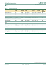
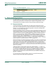
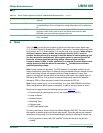
P1.6 P1M1.6 P1M2.6
P1.7 P1M1.7 P1M2.7
P3.0 P3M1.0 P3M2.0 CLKOUT, XTAL2
P3.1 P3M1.1 P3M2.1 XTAL1
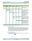
Table 10: Port output configuration
…continued
Port pin Configuration SFR bits
PxM1.y PxM2.y Alternate usage Notes