© Koninklijke Philips Electronics N.V. 2005. All rights reserved.
User manual Rev. 02 — 23 May 2005 72 of 133
Philips Semiconductors
UM10109
P89LPC932A1 User manual
11.4 I
2
C Status register
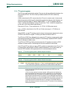
This is a read-only register. It contains the status code of the I
2
C interface. The least three
bits are always 0. There are 26 possible status codes. When the code is F8H, there is no
relevant information available and SI bit is not set. All other 25 status codes correspond to
defined I
2
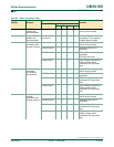
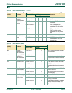
C states. When any of these states entered, the SI bit will be set. Refer to
Table 6 8
to Ta ble 71 for details.
11.5 I
2
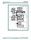
C SCL duty cycle registers I2SCLH and I2SCLL
When the internal SCL generator is selected for the I
2
C interface by setting CRSEL = 0 in
the I2CON register, the user must set values for registers I2SCLL and I2SCLH to select
the data rate. I2SCLH defines the number of PCLK cycles for SCL = high, I2SCLL defines
the number of PCLK cycles for SCL = low. The frequency is determined by the following
formula:
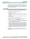
Bit Frequency = f
PCLK
/ (2*(I2SCLH + I2SCLL))
Where f
PCLK
is the frequency of PCLK.
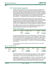
3SI I
2
C Interrupt Flag. This bit is set when one of the 25 possible I
2
C states is entered.
When EA bit and EI2C (IEN1.0) bit are both set, an interrupt is requested when SI
is set. Must be cleared by software by writing 0 to this bit.
4 STO STOP Flag. STO = 1: In master mode, a STOP condition is transmitted to the
I
2
C-bus. When the bus detects the STOP condition, it will clear STO bit
automatically. In slave mode, setting this bit can recover from an error condition. In
this case, no STOP condition is transmitted to the bus. The hardware behaves as if
a STOP condition has been received and it switches to ‘not addressed’ Slave
Receiver Mode. The STO flag is cleared by hardware automatically.
5 STA Start Flag. STA = 1: I
2
C-bus enters master mode, checks the bus and generates a
START condition if the bus is free. If the bus is not free, it waits for a STOP
condition (which will free the bus) and generates a START condition after a delay
of a half clock period of the internal clock generator. When the I
2
C interface is
already in master mode and some data is transmitted or received, it transmits a
repeated START condition. STA may be set at any time, it may also be set when
the I
2
C interface is in an addressed slave mode. STA = 0: no START condition or
repeated START condition will be generated.
6I2EN I
2
C Interface Enable. When set, enables the I
2
C interface. When clear, the I
2
C
function is disabled.
7- reserved
Table 62: I
2
C Control register (I2CON - address D8h) bit description …continued
Bit Symbol Description
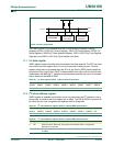
Table 63: I
2
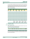
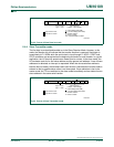
C Status register (I2STAT - address D9h) bit allocation
Bit 7 6 5 4 3 2 1 0
Symbol STA.4 STA.3 STA.2 STA.1 STA.0 0 0 0
Reset00000000
Table 64: I
2
C Status register (I2STAT - address D9h) bit description
Bit Symbol Description
0:2 - Reserved, are always set to 0.
3:7 STA[0:4] I
2
C Status code.


