


© Koninklijke Philips Electronics N.V. 2005. All rights reserved.
User manual Rev. 02 — 23 May 2005 57 of 133
Philips Semiconductors
UM10109
P89LPC932A1 User manual
Table 41: CCU interrupt status encode register (TISE2 - address DEh) bit description
Bit Symbol Description
2:0 ENCINT.2:0 CCU Interrupt Encode output. When multiple interrupts happen, more than one interrupt flag is set in
CCU Interrupt Flag Register (TIFR2). The encoder output can be read to determine which interrupt is
to be serviced. The user must write a logic 0 to clear the corresponding interrupt flag bit in the TIFR2
register after the corresponding interrupt has been serviced. Refer to Ta ble 43
for TIFR2 description.
000 — No interrupt pending.
001 — Output Compare Event D interrupt (lowest priority)
010 — Output Compare Event C interrupt.
011 — Output Compare Event B interrupt.
100 — Output Compare Event A interrupt.
101 — Input Capture Event B interrupt.
110 — Input Capture Event A interrupt.
111 — CCU Timer Overflow interrupt (highest priority).
3:7 - Reserved.
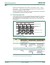
Table 42: CCU interrupt flag register (TIFR2 - address E9h) bit allocation
Bit 7 6 5 4 3 2 1 0
Symbol TOIF2 TOCF2D TOCF2C TOCF2B TOCF2A - TICF2B TICF2A
Reset00000x00
Table 43: CCU interrupt flag register (TIFR2 - address E9h) bit description
Bit Symbol Description
0 TICF2A Input Capture Channel A Interrupt Flag Bit. Set by hardware when an input capture event is detected.
Cleared by software.
1 TICF2B Input Capture Channel B Interrupt Flag Bit. Set by hardware when an input capture event is detected.
Cleared by software.
2 - Reserved for future use. Should not be set to logic 1 by user program.
3 TOCF2A Output Compare Channel A Interrupt Flag Bit. Set by hardware when the contents of TH2:TL2 match that
of OCRHA:OCRLA. Compare channel A must be enabled in order to generate this interrupt. If EA bit in
IEN0, ECCU bit in IEN1 and TOCIE2A bit are all set, the program counter will vectored to the
corresponding interrupt. Cleared by software.
4 TOCF2B Output Compare Channel B Interrupt Flag Bit. Set by hardware when the contents of TH2:TL2 match that
of OCRHB:OCRLB. Compare channel B must be enabled in order to generate this interrupt. If EA bit in
IEN0, ECCU bit in IEN1 and TOCIE2B bit are set, the program counter will vectored to the corresponding
interrupt. Cleared by software.
5 TOCF2C Output Compare Channel C Interrupt Flag Bit. Set by hardware when the contents of TH2:TL2 match that
of OCRHC:OCRLC. Compare channel C must be enabled in order to generate this interrupt. If EA bit in
IEN0, ECCU bit in IEN1 and TOCIE2C bit are all set, the program counter will vectored to the
corresponding interrupt. Cleared by software.
6 TOCF2D Output Compare Channel D Interrupt Flag Bit. Set by hardware when the contents of TH2:TL2 match that
of OCRHD:OCRLD. Compare channel D must be enabled in order to generate this interrupt. If EA bit in
IEN0, ECCU bit in IEN1 and TOCIE2D bit are all set, the program counter will vectored to the
corresponding interrupt. Cleared by software.
7 TOIF2 CCU Timer Overflow Interrupt Flag bit. Set by hardware on CCU Timer overflow. Cleared by software.