


© Koninklijke Philips Electronics N.V. 2005. All rights reserved.
User manual Rev. 02 — 23 May 2005 110 of 133
Philips Semiconductors
UM10109
P89LPC932A1 User manual
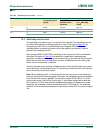
• FMADRL, FMADRH (Flash memory address low, Flash memory address high). Used
to specify the byte address within the page register or specify the page within user
code memory
• FMDATA (Flash Data Register). Accepts data to be loaded into the page register.
The page register consists of 64 bytes and an update flag for each byte. When a LOAD
command is issued to FMCON the page register contents and all of the update flags will
be cleared. When FMDATA is written, the value written to FMDATA will be stored in the
page register at the location specified by the lower 6 bits of FMADRL. In addition, the
update flag for that location will be set. FMADRL will auto-increment to the next location.
Auto-increment after writing to the last byte in the page register will ‘wrap-around’ to the
first byte in the page register, but will not affect FMADRL[7:6]. Bytes loaded into the page
register do not have to be continuous. Any byte location can be loaded into the page
register by changing the contents of FMADRL prior to writing to FMDATA. However, each
location in the page register can only be written once following each LOAD command.
Attempts to write to a page register location more than once should be avoided.
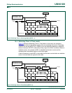
FMADRH and FMADRL[7:6] are used to select a page of code memory for the
erase-program function. When the erase-program command is written to FMCON, the
locations within the code memory page that correspond to updated locations in the page
register, will have their contents erased and programmed with the contents of their
corresponding locations in the page register. Only the bytes that were loaded into the
page register will be erased and programmed in the user code array. Other bytes within
the user code memory will not be affected.
Writing the erase-program command (68H) to FMCON will start the erase-program
process and place the CPU in a program-idle state. The CPU will remain in this idle state
until the erase-program cycle is either completed or terminated by an interrupt. When the
program-idle state is exited FMCON will contain status information for the cycle.
If an interrupt occurs during an erase/programming cycle, the erase/programming cycle
will be aborted and the OI flag (Operation Interrupted) in FMCON will be set. If the
application permits interrupts during erasing-programming the user code should check the
OI flag (FMCON.0) after each erase-programming operation to see if the operation was
aborted. If the operation was aborted, the user’s code will need to repeat the process
starting with loading the page register.
The erase-program cycle takes 4 ms (2 ms for erase, 2 ms for programming) to complete,
regardless of the number of bytes that were loaded into the page register.
Erasing-programming of a single byte (or multiple bytes) in code memory is accomplished
using the following steps:
• Write the LOAD command (00H) to FMCON. The LOAD command will clear all
locations in the page register and their corresponding update flags.
• Write the address within the page register to FMADRL. Since the loading the page
register uses FMADRL[5:0], and since the erase-program command uses FMADRH
and FMADRL[7:6], the user can write the byte location within the page register
(FMADRL[5:0]) and the code memory page address (FMADRH and FMADRL[7:6]) at
this time.
• Write the data to be programmed to FMDATA. This will increment FMADRL pointing to
the next byte in the page register.