


© Koninklijke Philips Electronics N.V. 2005. All rights reserved.
User manual Rev. 02 — 23 May 2005 68 of 133
Philips Semiconductors
UM10109
P89LPC932A1 User manual
10.20 Automatic address recognition
Automatic address recognition is a feature which allows the UART to recognize certain
addresses in the serial bit stream by using hardware to make the comparisons. This
feature saves a great deal of software overhead by eliminating the need for the software to
examine every serial address which passes by the serial port. This feature is enabled by
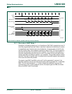
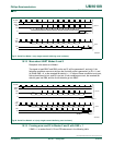
setting the SM2 bit in SCON. In the 9 bit UART modes (mode 2 and mode 3), the Receive
Interrupt flag (RI) will be automatically set when the received byte contains either the
‘Given’ address or the ‘Broadcast’ address. The 9 bit mode requires that the 9th
information bit is a 1 to indicate that the received information is an address and not data.
Using the Automatic Address Recognition feature allows a master to selectively
communicate with one or more slaves by invoking the Given slave address or addresses.
All of the slaves may be contacted by using the Broadcast address. Two special Function
Registers are used to define the slave’s address, SADDR, and the address mask,
SADEN. SADEN is used to define which bits in the SADDR are to be used and which bits
are ‘don’t care’. The SADEN mask can be logically ANDed with the SADDR to create the
‘Given’ address which the master will use for addressing each of the slaves. Use of the
Given address allows multiple slaves to be recognized while excluding others. The
following examples will help to show the versatility of this scheme:
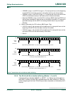
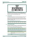
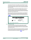
In the above example SADDR is the same and the SADEN data is used to differentiate
between the two slaves. Slave 0 requires a 0 in bit 0 and it ignores bit 1. Slave 1 requires
a 0 in bit 1 and bit 0 is ignored. A unique address for Slave 0 would be 1100 0010 since
slave 1 requires a 0 in bit 1. A unique address for slave 1 would be 1100 0001 since a 1 in
bit 0 will exclude slave 0. Both slaves can be selected at the same time by an address
which has bit 0 = 0 (for slave 0) and bit 1 = 0 (for slave 1). Thus, both could be addressed
with 1100 0000.
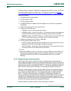
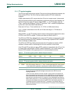
In a more complex system the following could be used to select slaves 1 and 2 while
excluding slave 0:
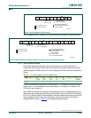
In the above example the differentiation among the 3 slaves is in the lower 3 address bits.
Slave 0 requires that bit 0 = 0 and it can be uniquely addressed by 1110 0110. Slave 1
requires that bit 1 = 0 and it can be uniquely addressed by 1110 and 0101. Slave 2
requires that bit 2 = 0 and its unique address is 1110 0011. To select Slaves 0 and 1 and
exclude Slave 2 use address 1110 0100, since it is necessary to make bit 2 = 1 to exclude
slave 2. The Broadcast Address for each slave is created by taking the logical OR of
SADDR and SADEN. Zeros in this result are treated as don’t-cares. In most cases,
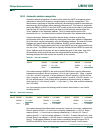
Table 56: Slave 0/1 examples
Example 1 Example 2
Slave 0 SADDR = 1100 0000 Slave 1 SADDR = 1100 0000
SADEN = 1111 1101 SADEN = 1111 1110
Given = 1100 00X0 Given = 1100 000X
Table 57: Slave 0/1/2 examples
Example 1 Example 2 Example 3
Slave 0 SADDR = 1100 0000 Slave 1 SADDR = 1110 0000 Slave 2 SADDR = 1100 0000
SADEN = 1111 1001 SADEN = 1111 1010 SADEN = 1111 1100
Given = 1100
0XX0
Given = 1110 0X0X Given = 1110 00XX