


© Koninklijke Philips Electronics N.V. 2005. All rights reserved.
User manual Rev. 02 — 23 May 2005 21 of 133
Philips Semiconductors
UM10109
P89LPC932A1 User manual
2. Clocks
2.1 Enhanced CPU
The P89LPC932A1 uses an enhanced 80C51 CPU which runs at six times the speed of
standard 80C51 devices. A machine cycle consists of two CPU clock cycles, and most
instructions execute in one or two machine cycles.
2.2 Clock definitions
The P89LPC932A1 device has several internal clocks as defined below:
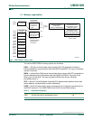
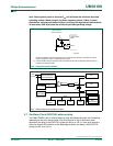
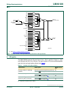
OSCCLK — Input to the DIVM clock divider. OSCCLK is selected from one of four clock
sources and can also be optionally divided to a slower frequency (see Figure 6
and
Section 2.8 “
CPU Clock (CCLK) modification: DIVM register”). Note: f
osc
is defined as the
OSCCLK frequency.
CCLK — CPU clock; output of the DIVM clock divider. There are two CCLK cycles per
machine cycle, and most instructions are executed in one to two machine cycles (two or
four CCLK cycles).
RCCLK — The internal 7.373 MHz RC oscillator output.
PCLK — Clock for the various peripheral devices and is
CCLK
⁄
2
.
2.2.1 Oscillator Clock (OSCCLK)
The P89LPC932A1 provides several user-selectable oscillator options. This allows
optimization for a range of needs from high precision to lowest possible cost. These
options are configured when the FLASH is programmed and include an on-chip watchdog
oscillator, an on-chip RC oscillator, an oscillator using an external crystal, or an external
clock source. The crystal oscillator can be optimized for low, medium, or high frequency
crystals covering a range from 20 kHz to 12 MHz.
2.2.2 Low speed oscillator option
This option supports an external crystal in the range of 20 kHz to 100 kHz. Ceramic
resonators are also supported in this configuration.
2.2.3 Medium speed oscillator option
This option supports an external crystal in the range of 100 kHz to 4 MHz. Ceramic
resonators are also supported in this configuration.
2.2.4 High speed oscillator option
This option supports an external crystal in the range of 4 MHz to 12 MHz. Ceramic
resonators are also supported in this configuration.
2.3 Clock output
The P89LPC932A1 supports a user-selectable clock output function on the XTAL2 /
CLKOUT pin when the crystal oscillator is not being used. This condition occurs if a
different clock source has been selected (on-chip RC oscillator, watchdog oscillator,
external clock input on X1) and if the Real-time Clock is not using the crystal oscillator as
its clock source. This allows external devices to synchronize to the P89LPC932A1. This
output is enabled by the ENCLK bit in the TRIM register