


© Koninklijke Philips Electronics N.V. 2005. All rights reserved.
User manual Rev. 02 — 23 May 2005 48 of 133
Philips Semiconductors
UM10109
P89LPC932A1 User manual
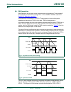
Up-counting: When the timer contents are FFFFH, the next CCUCLK cycle will set the
counter value to the contents of TOR2H:TOR2L.
Down-counting: When the timer contents are 0000H, the next CCUCLK cycle will set the
counter value to the contents of TOR2H:TOR2L. During the CCUCLK cycle when the
reload is performed, the CCU Timer Overflow Interrupt Flag (TOIF2) in the CCU Interrupt
Flag Register (TIFR2) will be set, and, if the EA bit in the IEN0 register and ECCU bit in
the IEN1 register (IEN1.4) are set, program execution will vector to the overflow interrupt.
The user has to clear the interrupt flag in software by writing a logic 0 to it.
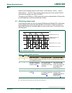
When writing to the reload registers, TOR2H and TOR2L, the values written are stored in
two 8-bit shadow registers. In order to latch the contents of the shadow registers into
TOR2H and TOR2L, the user must write a logic 1 to the CCU Timer Compare/Overflow
Update bit TCOU2, in CCU Timer Control Register 1 (TCR21). The function of this bit
depends on whether the timer is running in PWM mode or in basic timer mode. In basic
timer mode, writing a one to TCOU2 will cause the values to be latched immediately and
the value of TCOU2 will always read as zero. In PWM mode, writing a one to TCOU2 will
cause the contents of the shadow registers to be updated on the next CCU Timer
overflow. As long as the latch is pending, TCOU2 will read as one and will return to zero
when the latching takes place. TCOU2 also controls the latching of the Output Compare
registers OCR2A, OCR2B and OCR2C.
When writing to timer high byte, TH2, the value written is stored in a shadow register.
When TL2 is written, the contents of TH2’s shadow register is transferred to TH2 at the
same time that TL2 gets updated. Thus, TH2 should be written prior to writing to TL2. If a
write to TL2 is followed by another write to TL2, without TH2 being written in between, the
value of TH2 will be transferred directly to the high byte of the timer.
If the 16-bit CCU Timer is to be used as an 8-bit timer, the user can write FFh (for
upcounting) or 00h (for downcounting) to TH2. When TL2 is written, FFh:TH2 (for
upcounting) and 00h (for downcounting) will be loaded to CCU Timer. The user will not
need to rewrite TH2 again for an 8-bit timer operation unless there is a change in count
direction
When reading the timer, TL2 must be read first. When TL2 is read, the contents of the
timer high byte are transferred to a shadow register in the same PCLK cycle as the read is
performed. When TH2 is read, the contents of the shadow register are read instead. If a
read from TL2 is followed by another read from TL2 without TH2 being read in between,
the high byte of the timer will be transferred directly to TH2.
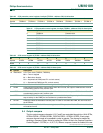
Table 28: CCU prescaler control register, high byte (TPCR2H - address CBh) bit allocation
Bit 7 6 5 4 3 2 1 0
Symbol------TPCR2H.1TPCR2H.0
Resetxxxxxx00
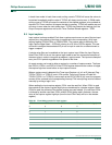
Table 29: CCU prescaler control register, high byte (TPCR2H - address CBh) bit description
Bit Symbol Description
0 TPCR2H.0 Prescaler bit 8
1 TPCR2H.1 Prescaler bit 9