


© Koninklijke Philips Electronics N.V. 2005. All rights reserved.
User manual Rev. 02 — 23 May 2005 37 of 133
Philips Semiconductors
UM10109
P89LPC932A1 User manual
• For any other reset, any previously set flag bits that have not been cleared will remain
set.
[1] The value shown is for a power-on reset. Other reset sources will set their corresponding bits.
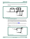
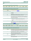
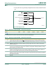
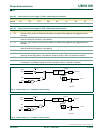
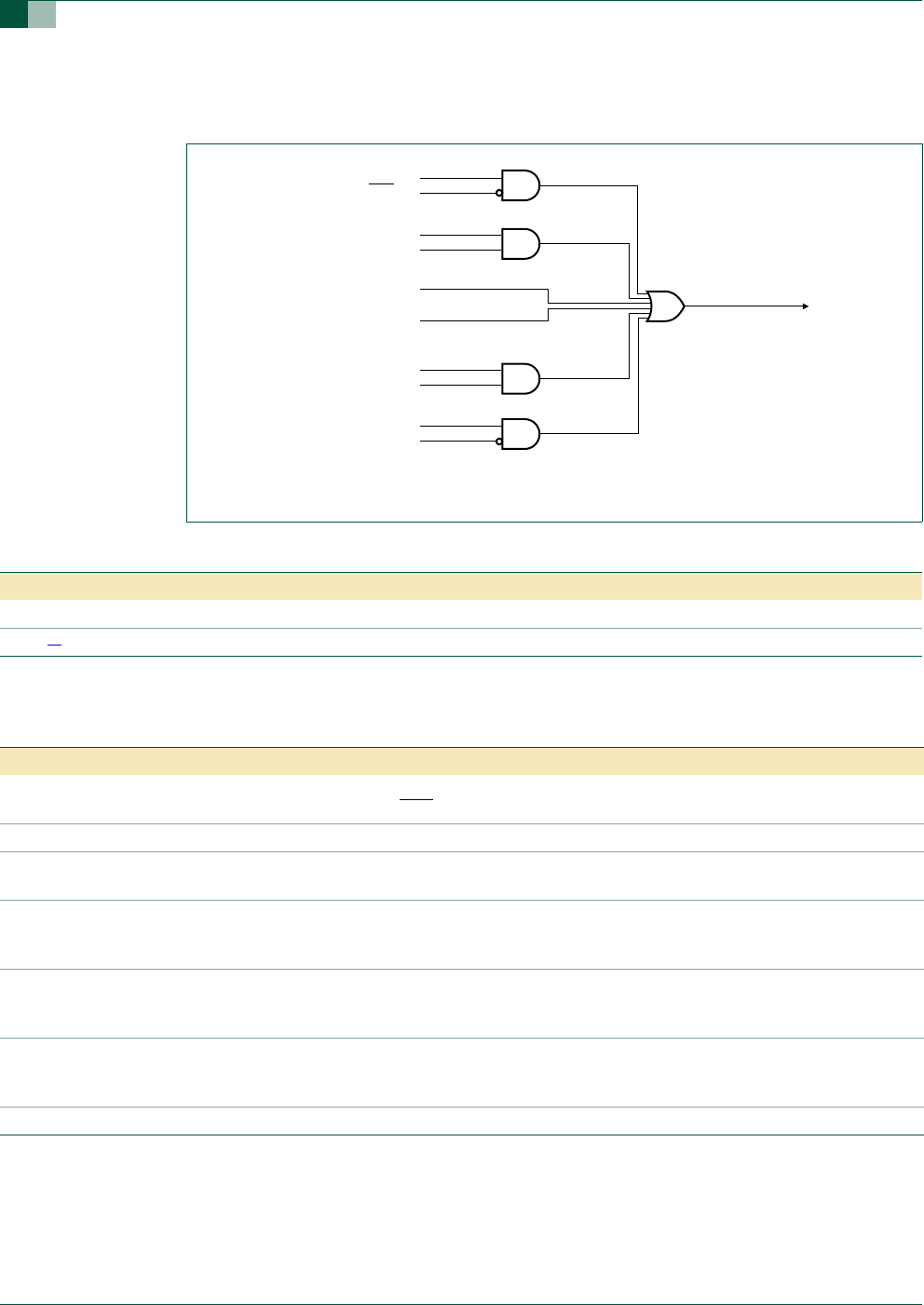
Fig 13. Block diagram of reset.
RPE (UCFG1.6)
RST pin
WDTE (UCFG1.7)
watchdog timer reset
software reset SRST (AUXR1.3)
power-on detect
UART break detect
EBRR (AUXR1.6)
brownout detect reset
BOPD (PCON.5)
chip reset
002aaa91
8
Table 17: Reset Sources register (RSTSRC - address DFh) bit allocation
Bit 7 6 5 4 3 2 1 0
Symbol - - BOF POF R_BK R_WD R_SF R_EX
Reset
[1]
xx110000
Table 18: Reset Sources register (RSTSRC - address DFh) bit description
Bit Symbol Description
0 R_EX external reset Flag. When this bit is logic 1, it indicates external pin reset. Cleared by software by writing a
logic 0 to the bit or a Power-on reset. If RST
is still asserted after the Power-on reset is over, R_EX will be set.
1 R_SF software reset Flag. Cleared by software by writing a logic 0 to the bit or a Power-on reset
2 R_WD Watchdog Timer reset flag. Cleared by software by writing a logic 0 to the bit or a Power-on reset.(NOTE:
UCFG1.7 must be = 1)
3 R_BK break detect reset. If a break detect occurs and EBRR (AUXR1.6) is set to logic 1, a system reset will occur.
This bit is set to indicate that the system reset is caused by a break detect. Cleared by software by writing a
logic 0 to the bit or on a Power-on reset.
4 POF Power-on Detect Flag. When Power-on Detect is activated, the POF flag is set to indicate an initial power-up
condition. The POF flag will remain set until cleared by software by writing a logic 0 to the bit. (Note: On a
Power-on reset, both BOF and this bit will be set while the other flag bits are cleared.)
5 BOF Brownout Detect Flag. When Brownout Detect is activated, this bit is set. It will remain set until cleared by
software by writing a logic 0 to the bit. (Note: On a Power-on reset, both POF and this bit will be set while the
other flag bits are cleared.)
6:7 - reserved