


© Koninklijke Philips Electronics N.V. 2005. All rights reserved.
User manual Rev. 02 — 23 May 2005 69 of 133
Philips Semiconductors
UM10109
P89LPC932A1 User manual
interpreting the don’t-cares as ones, the broadcast address will be FF hexadecimal. Upon
reset SADDR and SADEN are loaded with 0s. This produces a given address of all ‘don’t
cares’ as well as a Broadcast address of all ‘don’t cares’. This effectively disables the
Automatic Addressing mode and allows the microcontroller to use standard UART drivers
which do not make use of this feature.
11. I
2
C interface
The I
2
C-bus uses two wires, serial clock (SCL) and serial data (SDA) to transfer
information between devices connected to the bus, and has the following features:
• Bidirectional data transfer between masters and slaves
• Multimaster bus (no central master)
• Arbitration between simultaneously transmitting masters without corruption of serial
data on the bus
• Serial clock synchronization allows devices with different bit rates to communicate via
one serial bus
• Serial clock synchronization can be used as a handshake mechanism to suspend and
resume serial transfer
• The I
2
C-bus may be used for test and diagnostic purposes
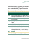
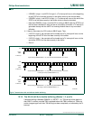
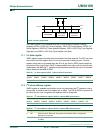
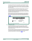
A typical I
2
C-bus configuration is shown in Figure 30. Depending on the state of the
direction bit (R/W), two types of data transfers are possible on the I
2
C-bus:
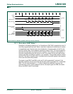
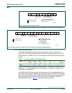
• Data transfer from a master transmitter to a slave receiver. The first byte transmitted
by the master is the slave address. Next follows a number of data bytes. The slave
returns an acknowledge bit after each received byte.
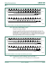
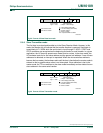
• Data transfer from a slave transmitter to a master receiver. The first byte (the slave
address) is transmitted by the master. The slave then returns an acknowledge bit.
Next follows the data bytes transmitted by the slave to the master. The master returns
an acknowledge bit after all received bytes other than the last byte. At the end of the
last received byte, a ‘not acknowledge’ is returned. The master device generates all of
the serial clock pulses and the START and STOP conditions. A transfer is ended with
a STOP condition or with a repeated START condition. Since a repeated START
condition is also the beginning of the next serial transfer, the I
2
C-bus will not be
released.
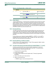
The P89LPC932A1 device provides a byte-oriented I
2
C interface. It has four operation
modes: Master Transmitter Mode, Master Receiver Mode, Slave Transmitter Mode and
Slave Receiver Mode