


© Koninklijke Philips Electronics N.V. 2005. All rights reserved.
User manual Rev. 02 — 23 May 2005 76 of 133
Philips Semiconductors
UM10109
P89LPC932A1 User manual
11.6.4 Slave Transmitter mode
The first byte is received and handled as in the Slave Receiver Mode. However, in this
mode, the direction bit will indicate that the transfer direction is reversed. Serial data is
transmitted via P1.3/SDA while the serial clock is input through P1.2/SCL. START and
STOP conditions are recognized as the beginning and end of a serial transfer. In a given
application, the I
2
C-bus may operate as a master and as a slave. In the slave mode, the
I
2
C hardware looks for its own slave address and the general call address. If one of these
addresses is detected, an interrupt is requested. When the microcontrollers wishes to
become the bus master, the hardware waits until the bus is free before the master mode is
entered so that a possible slave action is not interrupted. If bus arbitration is lost in the
master mode, the I
2
C-bus switches to the slave mode immediately and can detect its own
slave address in the same serial transfer.
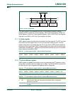
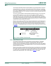
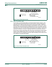
Fig 34. Format of Slave Receiver mode.
S W Aslave address
logic 0 = write
logic 1 = read
from master to slave
from slave to master
A = acknowledge (SDA LOW)
A = not acknowledge (SDA HIGH)
S = START condition
P = STOP condition
RS = repeated START condition
002aaa932
DATA DATA
data transferred
(n Bytes + acknowledge)
A A/A P/RS
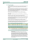
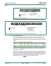
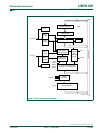
Fig 35. Format of Slave Transmitter mode.
S R Aslave address
logic 0 = write
logic 1 = read
from master to slave
from slave to master
A = acknowledge (SDA LOW)
A = not acknowledge (SDA HIGH)
S = START condition
P = STOP condition
002aaa933
DATA DATA
data transferred
(n Bytes + acknowledge)
A A P