


© Koninklijke Philips Electronics N.V. 2005. All rights reserved.
User manual Rev. 02 — 23 May 2005 64 of 133
Philips Semiconductors
UM10109
P89LPC932A1 User manual
10.12 More about UART Modes 2 and 3
Reception is the same as in Mode 1.
The signal to load SBUF and RB8, and to set RI, will be generated if, and only if, the
following conditions are met at the time the final shift pulse is generated. (a) RI = 0, and
(b) Either SM2 = 0, or the received 9th data bit = 1. If either of these conditions is not met,
the received frame is lost, and RI is not set. If both conditions are met, the received 9th
data bit goes into RB8, and the first 8 data bits go into SBUF.
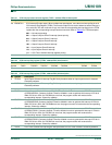
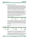
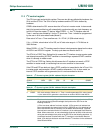
10.13 Framing error and RI in Modes 2 and 3 with SM2 = 1
If SM2 = 1 in modes 2 and 3, RI and FE behaves as in the following table.
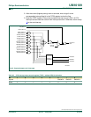
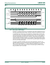
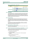
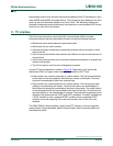
Fig 27. Serial Port Mode 1 (only single transmit buffering case is shown).
transmit
start
bit
stop bit
INTLO = 0
TX clock
write to
SBUF
shift
TxD
TI
D0 D1 D5D2 D6D3 D4 D7
receive
RX
clock
shift
RI
start
bit
stop bit
RxD
D0 D1 D5D2 D6D3 D4 D7
002aaa92
6
÷16 reset
INTLO = 1
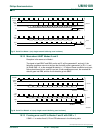
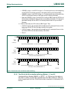
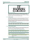
Fig 28. Serial Port Mode 2 or 3 (only single transmit buffering case is shown).
transmit
start
bit
stop bit
stop bit
TX clock
write to
SBUF
shift
TxD
TI
D0 D1 D5D2 D6D3 D4 D7
receive
RX
clock
shift
RI
start
bit
RxD
D0 D1 D5D2 D6D3 D4 D7
002aaa92
7
TB8
RB8
÷16 reset
INTLO = 0 INTLO = 1
SMOD0 = 0 SMOD0 = 1