


© Koninklijke Philips Electronics N.V. 2005. All rights reserved.
User manual Rev. 02 — 23 May 2005 75 of 133
Philips Semiconductors
UM10109
P89LPC932A1 User manual
After a repeated START condition, I
2
C-bus may switch to the Master Transmitter Mode.
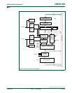
11.6.3 Slave Receiver mode
In the Slave Receiver Mode, data bytes are received from a master transmitter. To
initialize the Slave Receiver Mode, the user should write the slave address to the Slave
Address Register (I2ADR) and the I
2
C Control Register (I2CON) should be configured as
follows:
CRSEL is not used for slave mode. I2EN must be set = 1 to enable I
2
C function. AA bit
must be set = 1 to acknowledge its own slave address or the general call address. STA,
STO and SI are cleared to 0.
After I2ADR and I2CON are initialized, the interface waits until it is addressed by its own
address or general address followed by the data direction bit which is 0(W). If the direction
bit is 1(R), it will enter Slave Transmitter Mode. After the address and the direction bit have
been received, the SI bit is set and a valid status code can be read from the Status
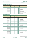
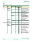
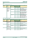
Register(I2STAT). Refer to Table 71
for the status codes and actions.
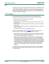
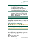
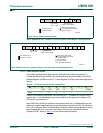
Fig 32. Format of Master Receiver mode.
S R Aslave address
logic 0 = write
logic 1 = read
from master to slave
from slave to master
A = acknowledge (SDA LOW)
A = not acknowledge (SDA HIGH)
S = START condition
002aaa93
0
DATA DATA
data transferred
(n Bytes + acknowledge)
A A P
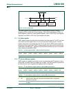
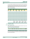
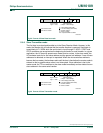
Fig 33. A Master Receiver switches to Master Transmitter after sending Repeated Start.
S R ASLA
logic 0 = write
logic 1 = read
from master to slave
from slave to master
002aaa931
DATA DATA
data transferred
(n Bytes + acknowledge)
A W ASLA DATA A PA RS
A = acknowledge (SDA LOW)
A = not acknowledge (SDA HIGH)
S = START condition
P = STOP condition
SLA = slave address
RS = repeat START condition
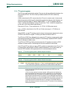
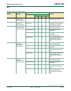
Table 67: I
2
C Control register (I2CON - address D8h)
Bit 7 6 5 4 3 2 1 0
- I2EN STA STO SI AA - CRSEL
value- 10001- -