


© Koninklijke Philips Electronics N.V. 2005. All rights reserved.
User manual Rev. 02 — 23 May 2005 11 of 133
Philips Semiconductors
UM10109
P89LPC932A1 User manual
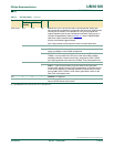
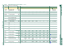
[1] Input/Output for P1.0 to P1.4, P1.6, P1.7. Input for P1.5.
P3.0 to P3.1 9, 8 5, 4 I/O Port 3: Port 3 is a 2-bit I/O port with a user-configurable output type.
During reset Port 3 latches are configured in the input only mode with the
internal pull-up disabled. The operation of Port 3 pins as inputs and
outputs depends upon the port configuration selected. Each port pin is
configured independently. Refer to Section 4.1
and the P89LPC932A1
data sheet, Static characteristics for details.
All pins have Schmitt triggered inputs.
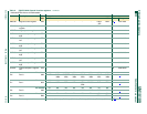
Port 3 also provides various special functions as described below:
95 I/OP3.0 — Port 3 bit 0.
O XTAL2 — Output from the oscillator amplifier (when a crystal oscillator
option is selected via the FLASH configuration.
O CLKOUT — CPU clock divided by 2 when enabled via SFR bit (ENCLK -
TRIM.6). It can be used if the CPU clock is the internal RC oscillator,
watchdog oscillator or external clock input, except when XTAL1/XTAL2
are used to generate clock source for the Real-Time clock/system timer.
84 I/OP3.1 — Port 3 bit 1.
I XTAL1 — Input to the oscillator circuit and internal clock generator
circuits (when selected via the FLASH configuration). It can be a port pin
if internal RC oscillator or watchdog oscillator is used as the CPU clock
source, and if XTAL1/XTAL2 are not used to generate the clock for the
Real-Time clock/system timer.
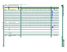
V
SS
73 IGround: 0 V reference.
V
DD
21 17 I Power Supply: This is the power supply voltage for normal operation as
well as Idle and Power-down modes.
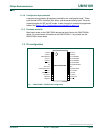
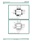
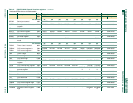
Table 1: Pin description
…continued
Symbol Pin Type Description
TSSOP28,
PLCC28
HVQFN28