


© Koninklijke Philips Electronics N.V. 2005. All rights reserved.
User manual Rev. 02 — 23 May 2005 104 of 133
Philips Semiconductors
UM10109
P89LPC932A1 User manual
15.5 Power-down operation
The WDT oscillator will continue to run in power-down, consuming approximately 50 µA,
as long as the WDT oscillator is selected as the clock source for the WDT. Selecting PCLK
as the WDT source will result in the WDT oscillator going into power-down with the rest of
the device (see Section 15.3
). Power-down mode will also prevent PCLK from running and
therefore the watchdog is effectively disabled.
15.6 Periodic wake-up from power-down without an external oscillator
Without using an external oscillator source, the power consumption required in order to
have a periodic wake-up is determined by the power consumption of the internal oscillator
source used to produce the wake-up. The Real-time clock running from the internal RC
oscillator can be used. The power consumption of this oscillator is approximately 300 µA.
Instead, if the WDT is used to generate interrupts the current is reduced to approximately
50 µA. Whenever the WDT underflows, the device will wake-up.
16. Additional features
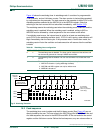
The AUXR1 register contains several special purpose control bits that relate to several
chip features. AUXR1 is described in Table 9 1
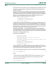
Table 90: AUXR1 register (address A2h) bit allocation
Bit 7 6 5 4 3 2 1 0
Symbol CLKLP EBRR ENT1 ENT0 SRST 0 - DPS
Reset000000x0
Table 91: AUXR1 register (address A2h) bit description
Bit Symbol Description
0 DPS Data Pointer Select. Chooses one of two Data Pointers.
1 - Not used. Allowable to set to a logic 1.
2 0 This bit contains a hard-wired 0. Allows toggling of the DPS bit by incrementing
AUXR1, without interfering with other bits in the register.
3 SRST Software Reset. When set by software, resets the P89LPC932A1 as if a hardware
reset occurred.
4 ENT0 When set the P1.2 pin is toggled whenever Timer 0 overflows. The output
frequency is therefore one half of the Timer 0 overflow rate. Refer to Section 7
“Timers 0 and 1” for details.
5 ENT1 When set, the P0.7 pin is toggled whenever Timer 1 overflows. The output
frequency is therefore one half of the Timer 1 overflow rate. Refer to Section 7
“Timers 0 and 1” for details.
6 EBRR UART Break Detect Reset Enable. If logic 1, UART Break Detect will cause a chip
reset and force the device into ISP mode.
7 CLKLP Clock Low Power Select. When set, reduces power consumption in the clock
circuits. Can be used when the clock frequency is 8 MHz or less. After reset this bit
is cleared to support up to 12 MHz operation.