


© Koninklijke Philips Electronics N.V. 2005. All rights reserved.
User manual Rev. 02 — 23 May 2005 101 of 133
Philips Semiconductors
UM10109
P89LPC932A1 User manual
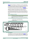
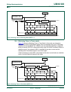
The maximum number of tclks is:
(3)
Table 8 9
shows sample P89LPC932A1 timeout values.
tclks 2
57+()
()255 1+()1 1048577=+=
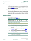
Table 87: Watchdog Timer Control register (WDCON - address A7h) bit allocation
Bit 7 6 5 4 3 2 1 0
Symbol PRE2 PRE1 PRE0 - - WDRUN WDTOF WDCLK
Reset111xx11/01
Table 88: Watchdog Timer Control register (WDCON - address A7h) bit description
Bit Symbol Description
0 WDCLK Watchdog input clock select. When set, the watchdog oscillator is selected. When cleared, PCLK is
selected. (If the CPU is powered down, the watchdog is disabled if WDCLK = 0, see Section 15.5
). (Note: If
both WDTE and WDSE are set to 1, this bit is forced to 1.) Refer to Section 15.3
for details.
1 WDTOF Watchdog Timer Time-Out Flag. This bit is set when the 8-bit down counter underflows. In watchdog mode,
a feed sequence will clear this bit. It can also be cleared by writing a logic 0 to this bit in software.
2 WDRUN Watchdog Run Control. The watchdog timer is started when WDRUN = 1 and stopped when WDRUN = 0.
This bit is forced to 1 (watchdog running) and cannot be cleared to zero if both WDTE and WDSE are set to
1.
3:4 - reserved
5PRE0
Clock Prescaler Tap Select. Refer to Table 89
for details.6PRE1
7PRE2
Table 89: Watchdog timeout vales
PRE2 to PRE0 WDL in decimal) Timeout Period
(in watchdog clock
cycles)
Watchdog Clock Source
400 KHz Watchdog
Oscillator Clock
(Nominal)
12 MHz CCLK (6 MHz
CCLK
⁄
2
Watchdog
Clock)
000 0 33 82.5 µs 5.50 µs
255 8,193 20.5 ms 1.37 ms
001 0 65 162.5 µs 10.8 µs
255 16,385 41.0 ms 2.73 ms
010 0 129 322.5 µs 21.5 µs
255 32,769 81.9 ms 5.46 ms
011 0 257 642.5 µs 42.8 µs
255 65,537 163.8 ms 10.9 ms
100 0 513 1.28 ms 85.5 µs
255 131,073 327.7 ms 21.8 ms
101 0 1,025 2.56 ms 170.8 µs
255 262,145 655.4 ms 43.7 ms