


© Koninklijke Philips Electronics N.V. 2005. All rights reserved.
User manual Rev. 02 — 23 May 2005 85 of 133
Philips Semiconductors
UM10109
P89LPC932A1 User manual
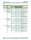
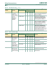
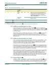
Table 73: SPI Control register (SPCTL - address E2h) bit description
Bit Symbol Description
0 SPR0 SPI Clock Rate Select
SPR1, SPR0:
00 —
CCLK
⁄
4
01 —
CCLK
⁄
16
10 —
CCLK
⁄
64
11 —
CCLK
⁄
128
1 SPR1
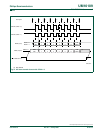
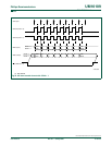
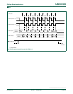
2 CPHA SPI Clock PHAse select (see Figure 41 to Figure 44):
1 — Data is driven on the leading edge of SPICLK, and is sampled on the trailing
edge.
0 — Data is driven when SS
is low (SSIG = 0) and changes on the trailing edge of
SPICLK, and is sampled on the leading edge. (Note: If SSIG = 1, the operation is
not defined.
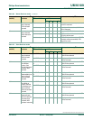
3 CPOL SPI Clock POLarity (see Figure 41
to Figure 44):
1 — SPICLK is high when idle. The leading edge of SPICLK is the falling edge and
the trailing edge is the rising edge.
0 — SPICLK is low when idle. The leading edge of SPICLK is the rising edge and
the trailing edge is the falling edge.
4 MSTR Master/Slave mode Select (see Tabl e 77).
5 DORD SPI Data ORDer.
1 — The LSB of the data word is transmitted first.
0 — The MSB of the data word is transmitted first.
6 SPEN SPI Enable.
1 — The SPI is enabled.
0 — The SPI is disabled and all SPI pins will be port pins.
7 SSIG SS IGnore.
1 — MSTR (bit 4) decides whether the device is a master or slave.
0 — The SS
pin decides whether the device is master or slave. The SS pin can be
used as a port pin (see Ta bl e 77
).
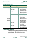
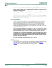
Table 74: SPI Status register (SPSTAT - address E1h) bit allocation
Bit 7 6 5 4 3 2 1 0
SymbolSPIFWCOL------
Reset00xxxxxx
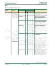
Table 75: SPI Status register (SPSTAT - address E1h) bit description
Bit Symbol Description
0:5 - reserved
6 WCOL SPI Write Collision Flag. The WCOL bit is set if the SPI data register, SPDAT, is
written during a data transfer (see Section 12.5 “
Write collision”). The WCOL flag
is cleared in software by writing a logic 1 to this bit.
7 SPIF SPI Transfer Completion Flag. When a serial transfer finishes, the SPIF bit is set
and an interrupt is generated if both the ESPI (IEN1.3) bit and the EA bit are set. If
SS
is an input and is driven low when SPI is in master mode, and SSIG = 0, this bit
will also be set (see Section 12.4 “
Mode change on SS”). The SPIF flag is cleared
in software by writing a logic 1 to this bit.