


© Koninklijke Philips Electronics N.V. 2005. All rights reserved.
User manual Rev. 02 — 23 May 2005 49 of 133
Philips Semiconductors
UM10109
P89LPC932A1 User manual
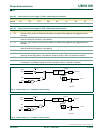
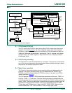
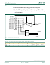
9.4 Output compare
The four output compare channels A, B, C and D are controlled through four 16-bit SFRs,
OCRAH:OCRAL, OCRBH:OCRBL, OCRCH:OCRCL, OCRDH: OCRDL. Each output
compare channel needs to be enabled in order to operate. The channel is enabled by
selecting a Compare Output Action by setting the OCMx1:0 bits in the Capture Compare x
Control Register – CCCRx (x = A, B, C, D). When a compare channel is enabled, the user
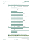
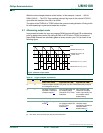
Table 30: CCU prescaler control register, low byte (TPCR2L - address CAh) bit allocation
Bit 7 6 5 4 3 2 1 0
Symbol TPCR2L.7 TPCR2L.6 TPCR2L.5 TPCR2L.4 TPCR2L.3 TPCR2L.2 TPCR2L.1 TPCR2L.0
Reset00000000
Table 31: CCU prescaler control register, low byte (TPCR2L - address CAh) bit description
Bit Symbol Description
0 TPCR2L.0 Prescaler bit 0
1 TPCR2L.1 Prescaler bit 1
2 TPCR2L.2 Prescaler bit 2
3 TPCR2L.3 Prescaler bit 3
4 TPCR2L.4 Prescaler bit 4
5 TPCR2L.5 Prescaler bit 5
6 TPCR2L.6 Prescaler bit 6
7 TPCR2L.7 Prescaler bit 7
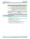
Table 32: CCU control register 0 (TCR20 - address C8h) bit allocation
Bit 7 6 5 4 3 2 1 0
Symbol PLLEN HLTRN HLTEN ALTCD ALTAB TDIR2 TMOD21 TMOD20
Reset00000000
Table 33: CCU control register 0 (TCR20 - address C8h) bit description
Bit Symbol Description
1:2 TMOD20/21 CCU Timer mode (TMOD21, TMOD20):
00 — Timer is stopped
01 — Basic timer function
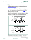
10 — Asymmetrical PWM (uses PLL as clock source)
11 — Symmetrical PWM (uses PLL as clock source)
2 TDIR2 Count direction of the CCU Timer. When logic 0, count up, When logic 1, count down.
3 ALTAB PWM channel A/B alternately output enable. When this bit is set, the output of PWM channel A and B
are alternately gated on every counter cycle.
4 ALTCD PWM channel C/D alternately output enable. When this bit is set, the output of PWM channel C and D
are alternately gated on every counter cycle.
5 HLTEN PWM Halt Enable. When logic 1, a capture event as enabled for Input Capture A pin will immediately
stop all activity on the PWM pins and set them to a predetermined state.
6 HLTRN PWM Halt. When set indicates a halt took place. In order to re-activate the PWM, the user must clear
the HLTRN bit.
7 PLLEN Phase Locked Loop Enable. When set to logic 1, starts PLL operation. After the PLL is in lock this bit it
will read back a one.