


© Koninklijke Philips Electronics N.V. 2005. All rights reserved.
User manual Rev. 02 — 23 May 2005 3 of 133
Philips Semiconductors
UM10109
P89LPC932A1 User manual
1. Introduction
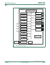
The P89LPC932A1 is a single-chip microcontroller designed for applications demanding
high-integration, low cost solutions over a wide range of performance requirements. The
P89LPC932A1 is based on a high performance processor architecture that executes
instructions in two to four clocks, six times the rate of standard 80C51 devices. Many
system-level functions have been incorporated into the P89LPC932A1 in order to reduce
component count, board space, and system cost.
1.1 Comparison to the P89LPC932 device
The P89LPC932A1 includes several improvements compared to the P89LPC932. These
improvements are described below.
1.1.1 Byte-erasability (IAP-Lite)
The original P89LPC932 allowed from 1 byte to 64 bytes of user code memory, in a single
page, to be programmed using an IAP function call. The bytes to be programmed needed
to have been previously erased using either a page erase, sector erase, or chip erase (in a
parallel programmer) command. Thus code memory was erased in 64 byte, 1 kB, or 8 kB
groups. The P89LPC932A1 allows from 1 byte to 64 bytes of a page of user code memory
to be erased and reprogrammed in a single operation. The bytes to be erased and
reprogrammed may be randomly addressed within a single page. Only the bytes so
addressed will be affected. See Section 18.4 “
Using Flash as data storage: IAP-Lite” on
page 109.
1.1.2 Serial in-circuit programming (ICP)
In-Circuit Programming is a method intended to allow low cost commercial programmers
to program and erase these devices without removing the microcontroller from the
system. The In-Circuit Programming facility consists of a series of internal hardware
resources to facilitate remote programming of the P89LPC932A1 through a two-wire serial
interface. Philips has made in-circuit programming in an embedded application possible
with a minimum of additional expense in components and circuit board area. The ICP
function uses five pins (V
DD
, V
SS
, P0.5, P0.4, and RST). Only a small connector needs to
be available to interface your application to an external programmer in order to use this
feature. This function was not available on the P89LPC932 device.
1.1.3 ‘On-the-fly’ clock selection
The RC Oscillator can be selected as the source for the CPU clock (CCLK) by using the
RCCLK bit in the TRIM register (TRIM.7). This bit allows for fast ‘on-the-fly’ switching
between the RC Oscillator and the clock source selected by the oscillator type select bits,
FOSC[2:0], in UCFG1, without the need to reset the device. This functionality was not
available on the P89LPC932. See Table 5 “
On-chip RC oscillator trim register (TRIM -
address 96h) bit description” on page 22.