


© Koninklijke Philips Electronics N.V. 2005. All rights reserved.
User manual Rev. 02 — 23 May 2005 87 of 133
Philips Semiconductors
UM10109
P89LPC932A1 User manual
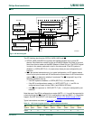
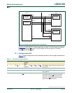
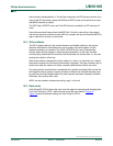
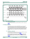
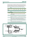
In Figure 40, SSIG (SPCTL.7) bits for the slaves are logic 0, and the slaves are selected
by the corresponding SS
signals. The SPI master can use any port pin (including
P2.4/SS
) to drive the SS pins.
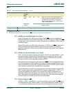
12.1 Configuring the SPI
Table 7 7 shows configuration for the master/slave modes as well as usages and directions
for the modes.
Fig 40. SPI single master multiple slaves configuration.
002aaa903
master slave
8-BIT SHIFT
REGISTER
SPI CLOCK
GENERATOR
8-BIT SHIFT
REGISTER
MISO
MOSI
SPICLK
port
port
MISO
MOSI
SPICLK
SS
slave
8-BIT SHIFT
REGISTER
MISO
MOSI
SPICLK
SS
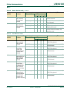
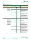
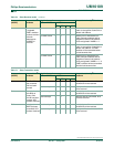
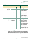
Table 77: SPI master and slave selection
SPEN SSIG SS Pin MSTR Master
or Slave
Mode
MISO MOSI SPICLK Remarks
0xP2.4
[1]
x SPI
Disabled
P2.3
[1]
P2.2
[1]
P2.5
[1]
SPI disabled. P2.2, P2.3, P2.4, P2.5 are used
as port pins.
1 0 0 0 Slave output input input Selected as slave.
1 0 1 0 Slave Hi-Z input input Not selected. MISO is high-impedance to avoid
bus contention.
1 0 0 1 (-> 0)
[2]
Slave output input input P2.4/SS is configured as an input or
quasi-bidirectional pin. SSIG is 0. Selected
externally as slave if SS
is selected and is
driven low. The MSTR bit will be cleared to
logic 0 when SS
becomes low.