


© Koninklijke Philips Electronics N.V. 2005. All rights reserved.
User manual Rev. 02 — 23 May 2005 58 of 133
Philips Semiconductors
UM10109
P89LPC932A1 User manual
10. UART
The P89LPC932A1 has an enhanced UART that is compatible with the conventional
80C51 UART except that Timer 2 overflow cannot be used as a baud rate source. The
P89LPC932A1 does include an independent Baud Rate Generator. The baud rate can be
selected from the oscillator (divided by a constant), Timer 1 overflow, or the independent
Baud Rate Generator. In addition to the baud rate generation, enhancements over the
standard 80C51 UART include Framing Error detection, break detect, automatic address
recognition, selectable double buffering and several interrupt options.
The UART can be operated in 4 modes, as described in the following sections.
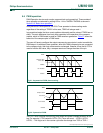
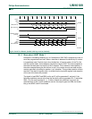
10.1 Mode 0
Serial data enters and exits through RxD. TxD outputs the shift clock. 8 bits are
transmitted or received, LSB first. The baud rate is fixed at
1
⁄
16
of the CPU clock frequency.
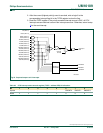
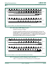
10.2 Mode 1
10 bits are transmitted (through TxD) or received (through RxD): a start bit (logic 0), 8
data bits (LSB first), and a stop bit (logic 1). When data is received, the stop bit is stored in
RB8 in Special Function Register SCON. The baud rate is variable and is determined by
the Timer 1 overflow rate or the Baud Rate Generator (see Section 10.6 “
Baud Rate
generator and selection” on page 59).
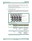
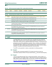
Table 44: CCU interrupt control register (TICR2 - address C9h) bit allocation
Bit 7 6 5 4 3 2 1 0
Symbol TOIE2 TOCIE2D TOCIE2C TOCIE2B TOCIE2A - TICIE2B TICIE2A
Reset00000x00
Table 45: CCU interrupt control register (TICR2 - address C9h) bit description
Bit Symbol Description
0 TICIE2A Input Capture Channel A Interrupt Enable Bit. If EA bit and this bit all be set, when a capture event is
detected, the program counter will vectored to the corresponding interrupt.
1 TICIE2B Input Capture Channel B Interrupt Enable Bit. If EA bit and this bit all be set, when a capture event is
detected, the program counter will vectored to the corresponding interrupt.
2 - Reserved for future use. Should not be set to logic 1 by user program.
3 TOCIE2A Output Compare Channel A Interrupt Enable Bit. If EA bit and this bit are set to 1, when compare channel
is enabled and the contents of TH2:TL2 match that of OCRHA:OCRLA, the program counter will vectored
to the corresponding interrupt.
4 TOCIE2B Output Compare Channel B Interrupt Enable Bit. If EA bit and this bit are set to 1, when compare channel
B is enabled and the contents of TH2:TL2 match that of OCRHB:OCRLB, the program counter will
vectored to the corresponding interrupt.
5 TOCIE2C Output Compare Channel C Interrupt Enable Bit. If EA bit and this bit are set to 1, when compare channel
C is enabled and the contents of TH2:TL2 match that of OCRHC:OCRLC, the program counter will
vectored to the corresponding interrupt.
6 TOCIE2D Output Compare Channel D Interrupt Enable Bit. If EA bit and this bit are set to 1, when compare channel
D is enabled and the contents of TH2:TL2 match that of OCRHD:OCRLD, the program counter will
vectored to the corresponding interrupt.
7 TOIE2 CCU Timer Overflow Interrupt Enable bit.