


© Koninklijke Philips Electronics N.V. 2005. All rights reserved.
User manual Rev. 02 — 23 May 2005 123 of 133
Philips Semiconductors
UM10109
P89LPC932A1 User manual
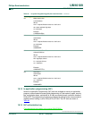
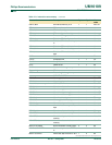
18.17 User configuration bytes
A number of user-configurable features of the P89LPC932A1 must be defined at
power-up and therefore cannot be set by the program after start of execution. These
features are configured through the use of an Flash byte UCFG1 shown in Table 10 1
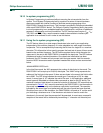
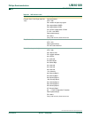
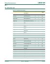
Read Sector CRC Input parameters:
ACC = 05h
R7= sector address
Return parameter(s):
R4= CRC bits 31:24
R5= CRC bits 23:16
R6= CRC bits 15:8
R7= CRC bits 7:0 (if no error)
R7= error status (if error)
Carry= set on error, clear on no error
Read Global CRC Input parameters:
ACC = 06h
Return parameter(s):
R4= CRC bits 31:24
R5= CRC bits 23:16
R6= CRC bits 15:8
R7= CRC bits 7:0 (if no error)
R7= error status (if error)
Carry= set on error, clear on no error
Read User Code Input parameters:
ACC = 07h
R4= address (MSB)
R5= address (LSB)
Return parameter(s):
R7= data
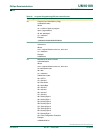
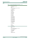
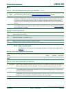
Table 99: IAP function calls
…continued
IAP function IAP call parameters
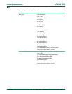
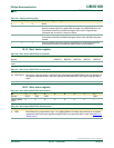
Table 100: Flash User Configuration Byte (UCFG1) bit allocation
Bit 7 6 5 4 3 2 1 0
Symbol WDTE RPE BOE WDSE - FOSC2 FOSC1 FOSC0
Unprogrammed
value
01100011
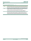
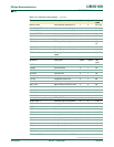
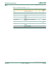
Table 101: Flash User Configuration Byte (UCFG1) bit description
Bit Symbol Description
0 FOSC0 CPU oscillator type select. See Section 2 “
Clocks” for additional information. Combinations other than those
shown in Tabl e 102
are reserved for future use should not be used.
1FOSC1
2FOSC2
3- reserved