© Koninklijke Philips Electronics N.V. 2005
All rights are reserved. Reproduction in whole or in part is prohibited without the prior
written consent of the copyright owner. The information presented in this document does
not form part of any quotation or contract, is believed to be accurate and reliable and may
be changed without notice. No liability will be accepted by the publisher for any
consequence of its use. Publication thereof does not convey nor imply any license under
patent- or other industrial or intellectual property rights.
Date of release: 23 May 2005
Published in the Netherlands
Philips Semiconductors
UM10109
P89LPC932A1 User manual
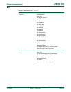
10.17 Transmit interrupts with double buffering enabled
(Modes 1, 2, and 3) . . . . . . . . . . . . . . . . . . . . 65
10.18 The 9th bit (bit 8) in double buffering (Modes 1, 2,
and 3) . . . . . . . . . . . . . . . . . . . . . . . . . . . . . . . 66
10.19 Multiprocessor communications . . . . . . . . . . . 67
10.20 Automatic address recognition . . . . . . . . . . . . 68
11 I
2
C interface . . . . . . . . . . . . . . . . . . . . . . . . . . . 69
11.1 I
2
C data register . . . . . . . . . . . . . . . . . . . . . . . 70
11.2 I
2
C slave address register. . . . . . . . . . . . . . . . 70
11.3 I
2
C control register . . . . . . . . . . . . . . . . . . . . . 71
11.4 I
2
C Status register . . . . . . . . . . . . . . . . . . . . . 72
11.5 I
2
C SCL duty cycle registers I2SCLH and
I2SCLL . . . . . . . . . . . . . . . . . . . . . . . . . . . . . . 72
11.6 I
2
C operation modes. . . . . . . . . . . . . . . . . . . . 73
11.6.1 Master Transmitter mode . . . . . . . . . . . . . . . . 73
11.6.2 Master Receiver mode . . . . . . . . . . . . . . . . . . 74
11.6.3 Slave Receiver mode . . . . . . . . . . . . . . . . . . . 75
11.6.4 Slave Transmitter mode . . . . . . . . . . . . . . . . . 76
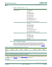
12 Serial Peripheral Interface (SPI) . . . . . . . . . . . 83
12.1 Configuring the SPI . . . . . . . . . . . . . . . . . . . . 87
12.2 Additional considerations for a slave . . . . . . . 88
12.3 Additional considerations for a master . . . . . . 88
12.4 Mode change on SS
. . . . . . . . . . . . . . . . . . . . 88
12.5 Write collision . . . . . . . . . . . . . . . . . . . . . . . . . 89
12.6 Data mode . . . . . . . . . . . . . . . . . . . . . . . . . . . 89
12.7 SPI clock prescaler select. . . . . . . . . . . . . . . . 93
13 Analog comparators . . . . . . . . . . . . . . . . . . . . 93
13.1 Comparator configuration . . . . . . . . . . . . . . . . 93
13.2 Internal reference voltage. . . . . . . . . . . . . . . . 95
13.3 Comparator input pins . . . . . . . . . . . . . . . . . . 95
13.4 Comparator interrupt . . . . . . . . . . . . . . . . . . . 95
13.5 Comparators and power reduction modes . . . 95
13.6 Comparators configuration example. . . . . . . . 96
14 Keypad interrupt (KBI). . . . . . . . . . . . . . . . . . . 97
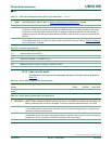
15 Watchdog timer (WDT) . . . . . . . . . . . . . . . . . . 98
15.1 Watchdog function . . . . . . . . . . . . . . . . . . . . . 98
15.2 Feed sequence. . . . . . . . . . . . . . . . . . . . . . . . 99
15.3 Watchdog clock source . . . . . . . . . . . . . . . . 102
15.4 Watchdog Timer in Timer mode . . . . . . . . . . 103
15.5 Power-down operation . . . . . . . . . . . . . . . . . 104
15.6 Periodic wake-up from power-down without an
external oscillator . . . . . . . . . . . . . . . . . . . . . 104
16 Additional features . . . . . . . . . . . . . . . . . . . . 104
16.1 Software reset. . . . . . . . . . . . . . . . . . . . . . . . 105
16.2 Dual Data Pointers . . . . . . . . . . . . . . . . . . . . 105
17 Data EEPROM. . . . . . . . . . . . . . . . . . . . . . . . . 105
17.1 Data EEPROM read . . . . . . . . . . . . . . . . . . . 106
17.2 Data EEPROM write. . . . . . . . . . . . . . . . . . . 107
17.3 Hardware reset . . . . . . . . . . . . . . . . . . . . . . . 107
17.4 Multiple writes to the DEEDAT register . . . . 107
17.5 Sequences of writes to DEECON and DEEDAT
registers . . . . . . . . . . . . . . . . . . . . . . . . . . . . 107
17.6 Data EEPROM Row Fill . . . . . . . . . . . . . . . . 107
17.7 Data EEPROM Block Fill . . . . . . . . . . . . . . . 108
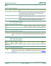
18 Flash memory . . . . . . . . . . . . . . . . . . . . . . . . 108
18.1 General description . . . . . . . . . . . . . . . . . . . 108
18.2 Features. . . . . . . . . . . . . . . . . . . . . . . . . . . . 108
18.3 Flash programming and erase . . . . . . . . . . . 109
18.4 Using Flash as data storage: IAP-Lite . . . . . 109
18.5 In-circuit programming (ICP) . . . . . . . . . . . . 113
18.6 ISP and IAP capabilities of the
P89LPC932A1 . . . . . . . . . . . . . . . . . . . . . . . 113
18.7 Boot ROM . . . . . . . . . . . . . . . . . . . . . . . . . . 113
18.8 Power on reset code execution . . . . . . . . . . 114
18.9 Hardware activation of Boot Loader. . . . . . . 114
18.10 In-system programming (ISP) . . . . . . . . . . . 115
18.11 Using the In-system programming (ISP) . . . 115
18.12 In-application programming (IAP) . . . . . . . . 118
18.13 IAP authorization key . . . . . . . . . . . . . . . . . . 118
18.14 Flash write enable . . . . . . . . . . . . . . . . . . . . 119
18.15 Configuration byte protection. . . . . . . . . . . . 119
18.16 IAP error status . . . . . . . . . . . . . . . . . . . . . . 120
18.17 User configuration bytes . . . . . . . . . . . . . . . 123
18.18 User security bytes . . . . . . . . . . . . . . . . . . . 124
18.19 Boot Vector register . . . . . . . . . . . . . . . . . . . 125
18.20 Boot status register . . . . . . . . . . . . . . . . . . . 125
19 Instruction set . . . . . . . . . . . . . . . . . . . . . . . . 127
20 Disclaimers . . . . . . . . . . . . . . . . . . . . . . . . . . 131
21 Trademarks . . . . . . . . . . . . . . . . . . . . . . . . . . 131


