


© Koninklijke Philips Electronics N.V. 2005. All rights reserved.
User manual Rev. 02 — 23 May 2005 114 of 133
Philips Semiconductors
UM10109
P89LPC932A1 User manual
18.8 Power on reset code execution
The P89LPC932A1 contains two special Flash elements: the BOOT VECTOR and the
Boot Status Bit. Following reset, the P89LPC932A1 examines the contents of the Boot
Status Bit. If the Boot Status Bit is set to zero, power-up execution starts at location
0000H, which is the normal start address of the user’s application code. When the Boot
Status Bit is set to a va one, the contents of the Boot Vector is used as the high byte of the
execution address and the low byte is set to 00H.
The factory default settings for this device is shown in Ta bl e 96
, below.
Note: These settings are different from the original P89LPC932.
The factory pre-programmed boot loader can be erased by the user. Users who wish to
use this loader should take cautions to avoid erasing the last 1 kB sector on the device.
Instead, the page erase function can be used to erase the eight 64-byte pages located in
this sector. A custom boot loader can be written with the Boot Vector set to the custom
boot loader, if desired.
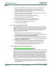
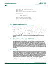
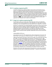
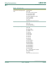
18.9 Hardware activation of Boot Loader
The boot loader can also be executed by forcing the device into ISP mode during a
power-on sequence (see Figure 50
). This is accomplished by powering up the device with
the reset pin initially held low and holding the pin low for a fixed time after V
DD
rises to its
normal operating value. This is followed by three, and only three, properly timed low-going
pulses. Fewer or more than three pulses will result in the device not entering ISP mode.
Timing specifications may be found in the data sheet for this device.
This has the same effect as having a non-zero status bit. This allows an application to be
built that will normally execute the user code but can be manually forced into ISP
operation. If the factory default setting for the Boot Vector is changed, it will no longer point
to the factory pre-programmed ISP boot loader code. If this happens, the only way it is
possible to change the contents of the Boot Vector is through the parallel or ICP
programming method, provided that the end user application does not contain a
customized loader that provides for erasing and reprogramming of the Boot Vector and
Boot Status Bit. After programming the Flash, the status byte should be programmed to
zero in order to allow execution of the user’s application code beginning at address
0000H.
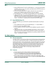
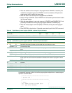
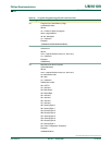
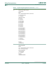
Table 96: Boot loader address and default Boot vector
Product Flash size End
address
Signature bytes Sector
size
Page
size
Pre-programmed
serial loader
Default Boot
vector
Mfg id Id 1 Id 2
P89LPC932A1 8 kB × 8 1FFFh 15h DDh 1Fh 1 kB × 864 × 8 1E00h to 1FFFh 1Fh
Fig 50. Forcing ISP mode.
002aaa912
V
DD
RST
t
RL
t
VR
t
RH