


© Koninklijke Philips Electronics N.V. 2005. All rights reserved.
User manual Rev. 02 — 23 May 2005 100 of 133
Philips Semiconductors
UM10109
P89LPC932A1 User manual
these two SFRs will not take effect. To avoid a watchdog reset, the watchdog timer needs
to be fed (via a special sequence of software action called the feed sequence) prior to
reaching an underflow.
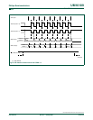
To feed the watchdog, two write instructions must be sequentially executed successfully.
Between the two write instructions, SFR reads are allowed, but writes are not allowed.
The instructions should move A5H to the WFEED1 register and then 5AH to the WFEED2
register. An incorrect feed sequence will cause an immediate watchdog reset. The
program sequence to feed the watchdog timer is as follows:
CLR EA ;disable interrupt
MOV WFEED1,#0A5h ;do watchdog feed part 1
MOV WFEED2,#05Ah ;do watchdog feed part 2
SETB EA ;enable interrupt
This sequence assumes that the P89LPC932A1 interrupt system is enabled and there is a
possibility of an interrupt request occurring during the feed sequence. If an interrupt was
allowed to be serviced and the service routine contained any SFR writes, it would trigger a
watchdog reset. If it is known that no interrupt could occur during the feed sequence, the
instructions to disable and re-enable interrupts may be removed.
In watchdog mode (WDTE = 1), writing the WDCON register must be IMMEDIATELY
followed by a feed sequence to load the WDL to the 8-bit down counter, and the WDCON
to the shadow register. If writing to the WDCON register is not immediately followed by the
feed sequence, a watchdog reset will occur.
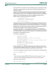
For example: setting WDRUN = 1:
MOV ACC,WDCON ;get WDCON
SETB ACC.2 ;set WD_RUN=1
MOV WDL,#0FFh ;New count to be loaded to 8-bit down counter
CLR EA ;disable interrupt
MOV WDCON,ACC ;write back to WDCON (after the watchdog is enabled, a feed
must occur ; immediately)
MOV WFEED1,#0A5h ;do watchdog feed part 1
MOV WFEED2,#05Ah ;do watchdog feed part 2
SETB EA ;enable interrupt
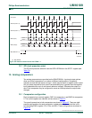
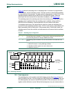
In timer mode (WDTE = 0), WDCON is loaded to the control register every CCLK cycle
(no feed sequence is required to load the control register), but a feed sequence is required
to load from the WDL SFR to the 8-bit down counter before a time-out occurs.
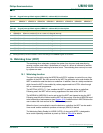
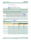
The number of watchdog clocks before timing out is calculated by the following equations:
(1)
where:
PRE is the value of prescaler (PRE2 to PRE0) which can be the range 0 to 7, and;
WDL is the value of watchdog load register which can be the range of 0 to 255.
The minimum number of tclks is:
(2)
tclks 2
5 PRE+()
()WDL 1+()1+=
tclks 2
50+()
()01+()133=+=