


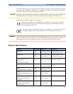

Monitor Performance Specifications 34 Installation and Specifications
345
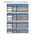
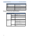
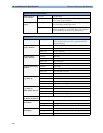
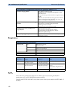
Monitor Interface Specifications
Network Standard IEEE 802.3 10-Base-T
Connector
RJ45 (8 pin)
Isolation
1.5 kV
Parallel Printer Port Standard IEEE 1284-I
Connector
DB-25
Signals
Level 1 and Level 2 (switchable)
Isolation
1.5 kV
Communication
Modes
Compatibility (for example Centronics), Nibble, ECP, EPP
Dual PS/2 Inputs Input Voltage 5V ±5%
Output Current
250mA (comb. max) to connected PS/2 devices
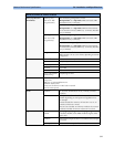
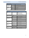
Dual MIB/RS232 Standard IEEE 1073-3.2-2000
Connectors
RJ45 (8 pin)
Mode
Software-controllable
BCC (RxD/TxD cross over) or
DCC (RxD/TxD straight through)
Power
5V +/- 5%, 100mA (max.)
Isolation
1.5kV
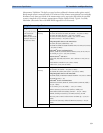
MIB-ready/RS-232
Interface
(not available in all
geographies)
Measurement data
exported to external
systems:
Numerics, alarms and INOPs, patient demographics, waves (up
to 7; maximum number depends on the sample rate of the
selected waves).
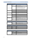
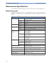
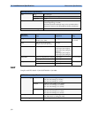
ECG Output/Marker Input (1/4” stereo phone jack with tip, ring, sleeve)
General Connector 1/4” phone each with tip, ring, sleeve
Isolation
500 V
ECG Output
(ring, tip)
Signal Gain 320 to 3200
Full Scale on Display
3.2V
pp
Gain Error <20%
Baseline Offset
<150mV
Bandwidth
1 to 80Hz
Output Impedance
ECG Output (ring): <2.2KΩ±20%
ECG Output/Marker Input (tip) <2.5kΩ ±20%
Signal delay ≤30ms
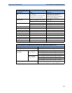
Marker Input
Requirements
(tip)
Signal Type
0 to -12V, negative edge pulse
Pulse Source
Impedance
<7kΩ
Pulse Fall Time
<100µs
Pulse Duration
>4ms
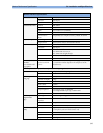
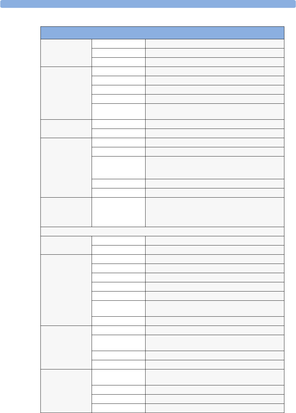
Flexible Nurse Call
Relay
Connector 20 pin MDR (Mini D-Ribbon), active open and closed contacts
3.5 mm phone jack, active closed contact only
Contact
<= 100 mA, <= 24 V DC
Isolation
1.5 kV
Delay
< (Configured Latency + 0.5 sec)