


15 Monitoring Airway Flow, Volume and Pressure Attaching the Flow Sensor
188
Attaching the Flow Sensor
CAUTION Use the M1014A Spirometry Module with Philips approved accessories only. Refer to the instructions
for use provided with the accessory.
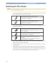
1 Select the appropriate flow sensor. Make sure that you are using the correct sensor for the respective
patient category. Otherwise accuracy may be reduced.
You can also use combined CO
2
/flow sensors. Note that the M3014A Capnography Extension is
required to measure CO
2
.
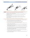
2 If you are using a combined CO
2
/Flow sensor, connect it to the CO
2
sensor head first. The airway
adapter clicks into place when seated correctly.
3 Click the connector into place in the flow sensor receptacle on the monitor before connecting to
the breathing circuit.
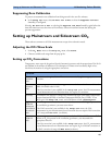
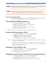
4 Install the flow sensor or the combined CO
2
/Flow sensor at the proximal end of the breathing
circuit between the elbow and the ventilator Y-piece. Make sure that the spirometry sensor is in a
horizontal position with its tubing pointing upwards. The correct position is also indicated by an
arrow on some of the sensors. (Graphic shows combined CO
2
/Flow Sensors).
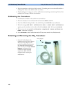
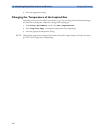
Pediatric/Adult Flow Sensor (M2785A). Color: clear
For intubated patients with endotracheal tube diameters >4 mm. Adds
approximately 6.5 cc of deadspace.
Infant/Neonatal Flow Sensor (M2786A) Color: violet
For intubated patients with endotracheal tube diameters ≤ 4 mm.
Adds less than 1 cc of deadspace.
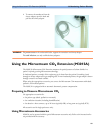
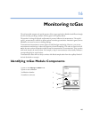
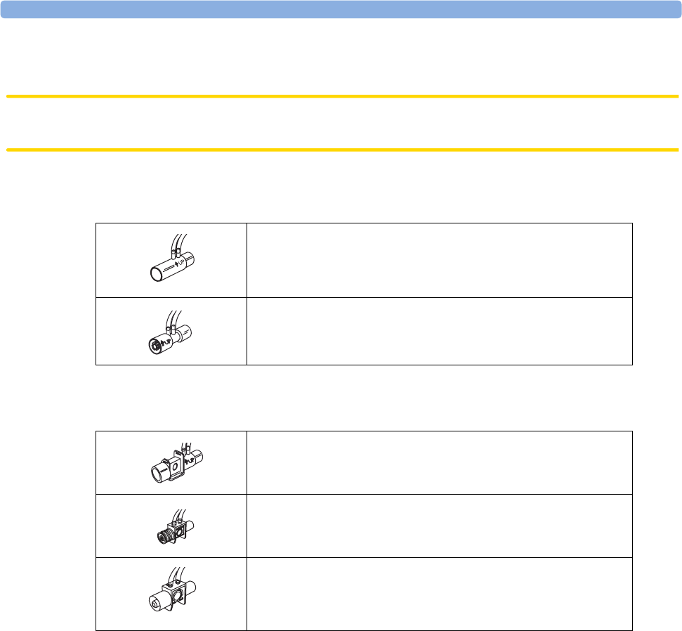
Pediatric/Adult Combined CO
2
/Flow Sensor (M2781A). Color: clear
For intubated patients with endotracheal tube diameters >5.5 mm.
Adds 8 cc of deadspace.
Pediatric Combined CO
2
/Flow Sensor (M2783A): Color: green
For intubated patients with endotracheal tube diameters of 3.5 -
6 mm. Adds less than 4 cc of deadspace.
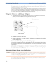
Infant/Neonatal Combined CO
2
/Flow Sensor (M2782A).
Color: violet
For intubated patients with endotracheal tube diameters of 2.5 -
4 mm. Adds less than 1 cc of deadspace.