


Using the EEG Impedance/Montage Window 18 Monitoring EEG
209
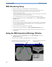
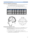
Choosing an EEG Electrode Montage
1 To activate one of the five pre-configured electrode montages, select the arrow beside the label in
the EEG Impedance/Montage window and choose a montage from the list.
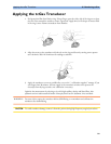
2 Attach the electrodes as illustrated in the EEG Impedance/Montage window.
The five default electrode montage configurations can be modified and renamed in Configuration
Mode.
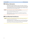
The electrode locations are labeled according to the international 10-20 electrode placement system.
Changing the Impedance Limit
The impedance limit can be set for all electrodes simultaneously in the Setup EEG menu, or in the
EEG Impedance/Montage window using the pop-up keys. If the limit is exceeded during
monitoring, an INOP will appear and the graphic impedance indicator will change.
To change the impedance limit, either
♦ use the pop-up keys that appear with the EEG Impedance /Montage window, or
♦ in the Setup EEG menu, select Impedance Limit to call up a list of selections between 1 and
30 kOhm, then select the required limit from this list.
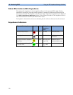
Montage Name EEG1+ EEG1- Label1 EEG2+ EEG2- Label2
Mont.A Fp1 T3 Fp1-T3 Fp2 T4 Fp2-T4
Mont.B O1 T3 O1-T3 O2 T4 O2-T4
Mont.C F3 C3 F3-C3 F4 C4 F4-C4
Mont.D C3 P3 C3-P3 C4 P4 C4-P4
Mont.E Fp1 T5 Fp1-T5 Fp2 T6 Fp2-T6